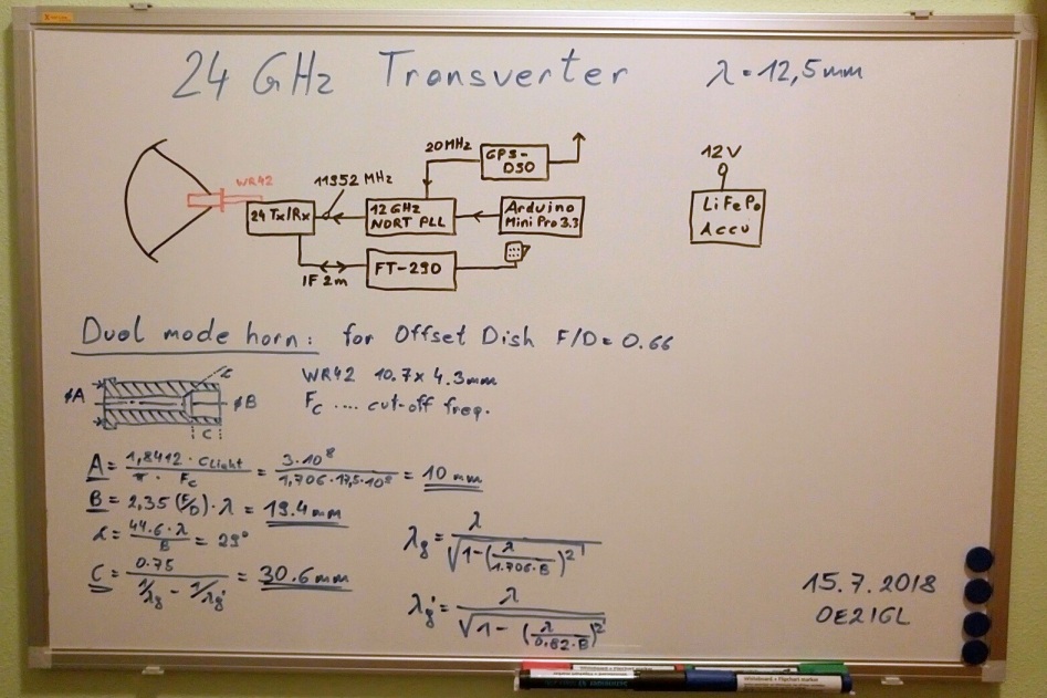
24 GHz transverter
My 24.048 GHz transverter is an easy and cheap solution with less Tx power. I use an old mixer design made by Michael DB6NT.
Only a few parts are needed.
A 12 GHz module, harmonic-mixer module, IF transmitter/receiver and an antenna.
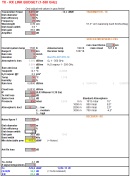
Click on image, download and extract my Excel sheet "Link budget v2.1" to calculate microwave links up to 1000 GHz. Calculation of atmospheric attenuation (ITU-R P.676-12) is included.
1. Offset dish and tripod with pan/tilt mount
Same design as for my 76 GHz transverter and pan/tilt head.
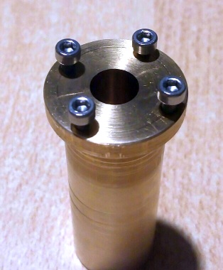
2. W2IMU dual mode feed horn
hdl_ant software by W1GHZ is a good choice to calculate a dual mode feed horn. It is a circular wave guide with a diameter of 10.1 mm and the aperture is 19.4 mm (depth of 30.6 mm).
Wave length = 12.5 mm
WR-42: 10.7 x 4.3 mm

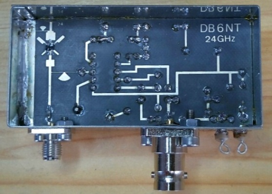
3. Transverter
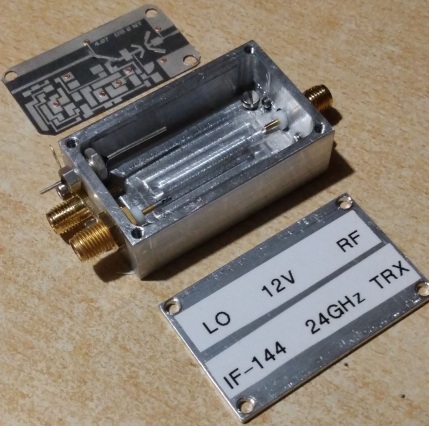
1st version: MK II transverter
I use this mixer
design from the 90s of last century.
RX NF = 8 dB (DSB)
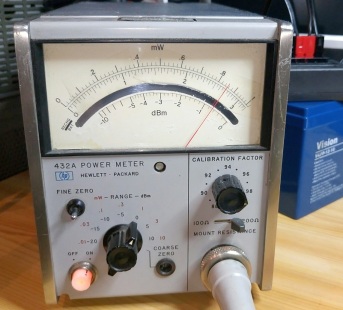
TX power max = 0.5 mW (SSB), 1.3 mW (DSB)
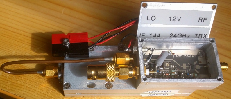
To get maximum TX output use short diode leads, mount both diodes "overhead" and flat on the PCB. I used
flags between diodes and waveguide pin. I reached 0.85 mW (DSB).
Needed external reference power is approx. 25-60 mW (14-18 dBm) @ 12 GHz
11952 * 2 + 144 IF = 24048 MHz


NORT PLL with arduino, transceiver with dual mode horn:

2nd version: MK III transverter
Again a DB6NT transverter with coax output. Size is only 44 x 24 mm and a I made a small aluminium housing 50 x 30 x 18 mm. Same performance as MK II.
Power consumption: 20 mA @12V
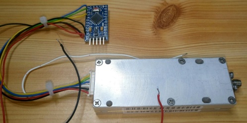
4. PLL with 11952 MHz output
1st solution:
I use a modified NORT PLL to obtain 11952 MHz for the transverter input. I removed the internal 20 MHz quartz and mounted a SMA connector which is an external
reference input now.
See more under electronics.
Output power : 13 dBm
ADF4153 parameters for reference frequency of 20 MHz. VCO output is 2988 MHz and this gives 2988 *4 = 11952 MHz for our mixer.

I prefer 23.715 MHz as reference frequency. The reason is that I use output B (locked to output A) of my GPSDO for my 76 GHz transverter and output
A for my 24 GHz transverter.

2nd solution:
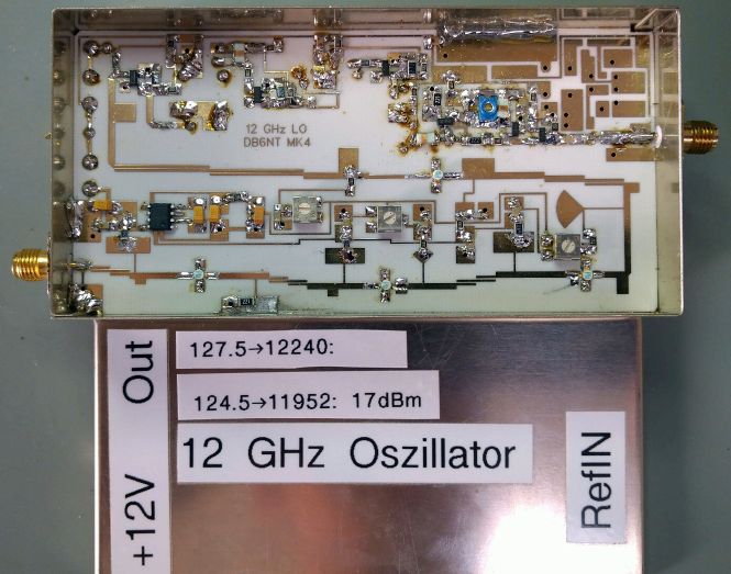
LO/2 power could be higher to get more power for the mixer and 24 GHz output. I built a 12 GHz LO module designed by DB6NT.
11.952 GHz ouput: 70 mW (18.5 dBm)
Current consumption @12V: 220 mA
5. New system with preamplifier, power amplifier and cavity filter
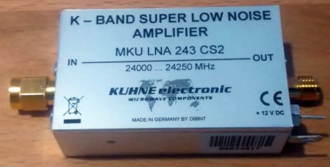
DB6NT preamplifier:
Noise figure: ~2 dB
Gain: 24 dB
Current consumption: 60 mA
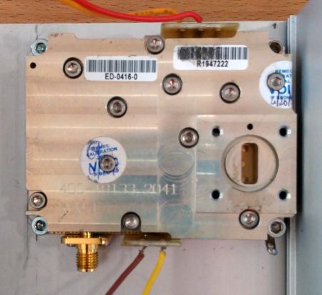
Power amplifier module:
I got this modified Ceragon REMEC ED-0416 PA module from OE2JOM. Gain is extremely high and therefore a low cost/performance transverter with low output power is sufficient.
Gain: ~50 dB
Output power: ~1.5 W
OE9PMJ cavity filter:
I got this used cavity filter from OE5VRL.

Assembled system:
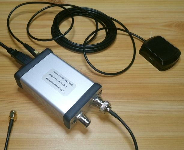
6. GPS disciplined reference oscillator to set PLL reference input
Here I use a nice unit by Leo Bodnar.
It has 2 separate outputs (3.3V CMOS level) from 450 Hz to 800 MHz and it uses GPS reveiver for very stable output frequency.
Output power up to 13.7 dBm
Current consumption @ 12V DC: 190 mA
7. IF receiver/transmitter
Therefore I use the good, old FT-290R.

8. Accu Pack
I use a 12V LiFePO4 accu with 10Ah because of its light weight, only 1.4 kg.
9. Test results
8th of November 2019: First successful 24 GHz (SSB, FM) test QSO.