Portable EME (earth moon earth) on 24.048 GHz
UNDER CONSTRUCTION. If have all needed parts, assembling is open.
EARTH-SPACE ATTENUATION & SKY TEMPERATURE:
Click HERE, download and extract my Excel sheet "Earth-Space-Attenuation" to calculate microwave earth-space attenuation and sky temperatur up to 350 GHz. Calculation of atmospheric attenuation (ITU-R P.676-12) is included. Either with local weather data only or with integrated water vapour content delivered by weather sonde data.
EME link budget and analysis tool:
Click HERE
1. Offset dish with azimuth/elevation drive
Therefore I use my 82 cm Gibertini offset dish with azimuth rotation system.
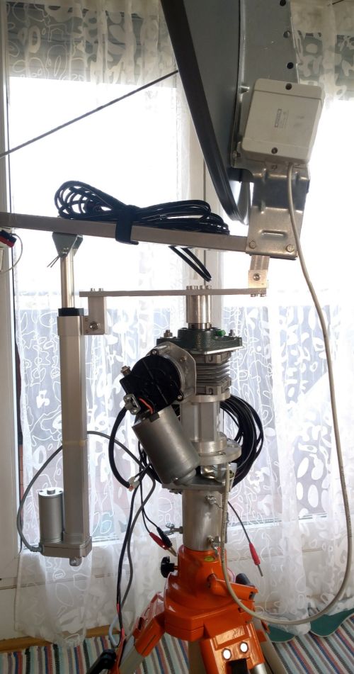
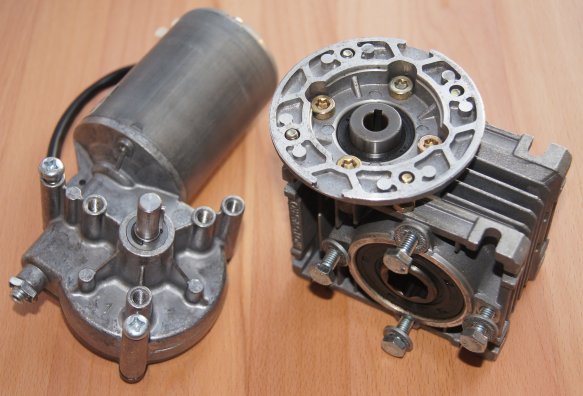
DC motor with encoder for azimuth (0 to 360°)
12V (5A, 5Nm, 40 rpm) worm gear motor (windshield wiper motor) with additional worm gear (20:1) to get 2 rpm.
Torque is approx. 100 Nm.
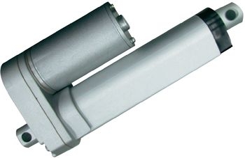
DC linear motor with encoder for elevation (0 to 90°)
Linear motor DSZY1-12-40-A-200-IP65.
Power supply: 12 V/DC
Speed: 8 mm/sec
Stroke length: 200 mm
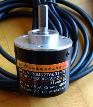
2. EA3HMJ dish rotor controller
At higher frequencies (>24 GHz) and/or bigger dishes the half-power-beam width is around or smaller than sun/moon diameter (0.5°).
Azimuth/elevation accuracy: <0.03°
![]()
![]()
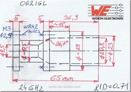
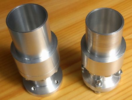
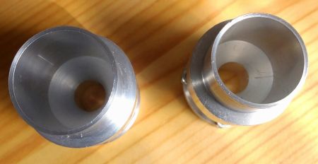
3. W2IMU dual mode feed horn
Slightly modified new version for better receive performance: f/D = 0.71
It is a circular wave guide with a diameter of 9.5 mm and the aperture is 20.8 mm (depth of 36.9 mm). As it is not easy to make inner 29° angle this horn consists of 2 parts.
Wave length = 12.5 mm
WR-42: 10.7 x 4.3 mm
Left: feed f/D = 0.66
Right: feed f/D = 0.71
4. Waveguide switch
In front of the feed horn I mounted a WR42 waveguide switch from SPINNER GmbH to minimize signal loss and to have a sufficient decoupling between Tx and Rx.
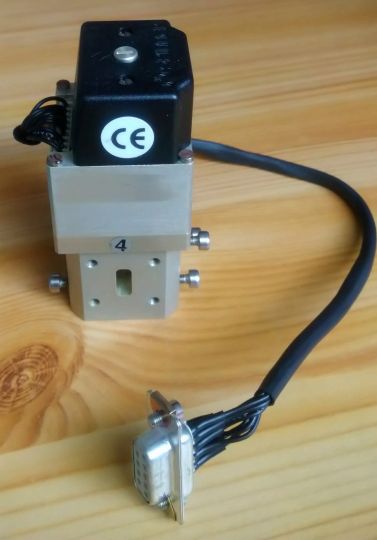
I use a WR42-to-CIR quarter-wave adapter plate to minimize return loss.
Thickness: 3.9 mm
Waveguide dimension: 10.1 x 6.25 mm using a ø5 mm milling cutter

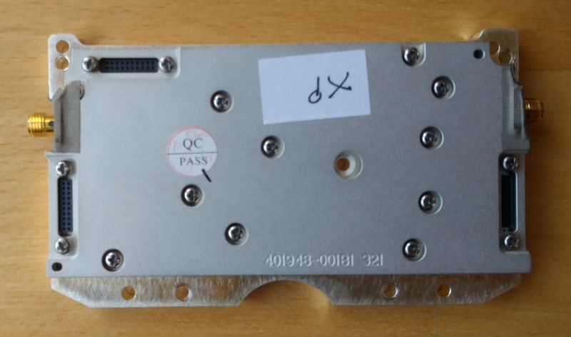
5. Transverter
It is a 23GHz WAVELAB 23x1008xp module bought on eBay.
Tx - PA: 21.2 - 23.6 GHz
Noise figure: 3.5 dB
Output power: max 2W
See here.
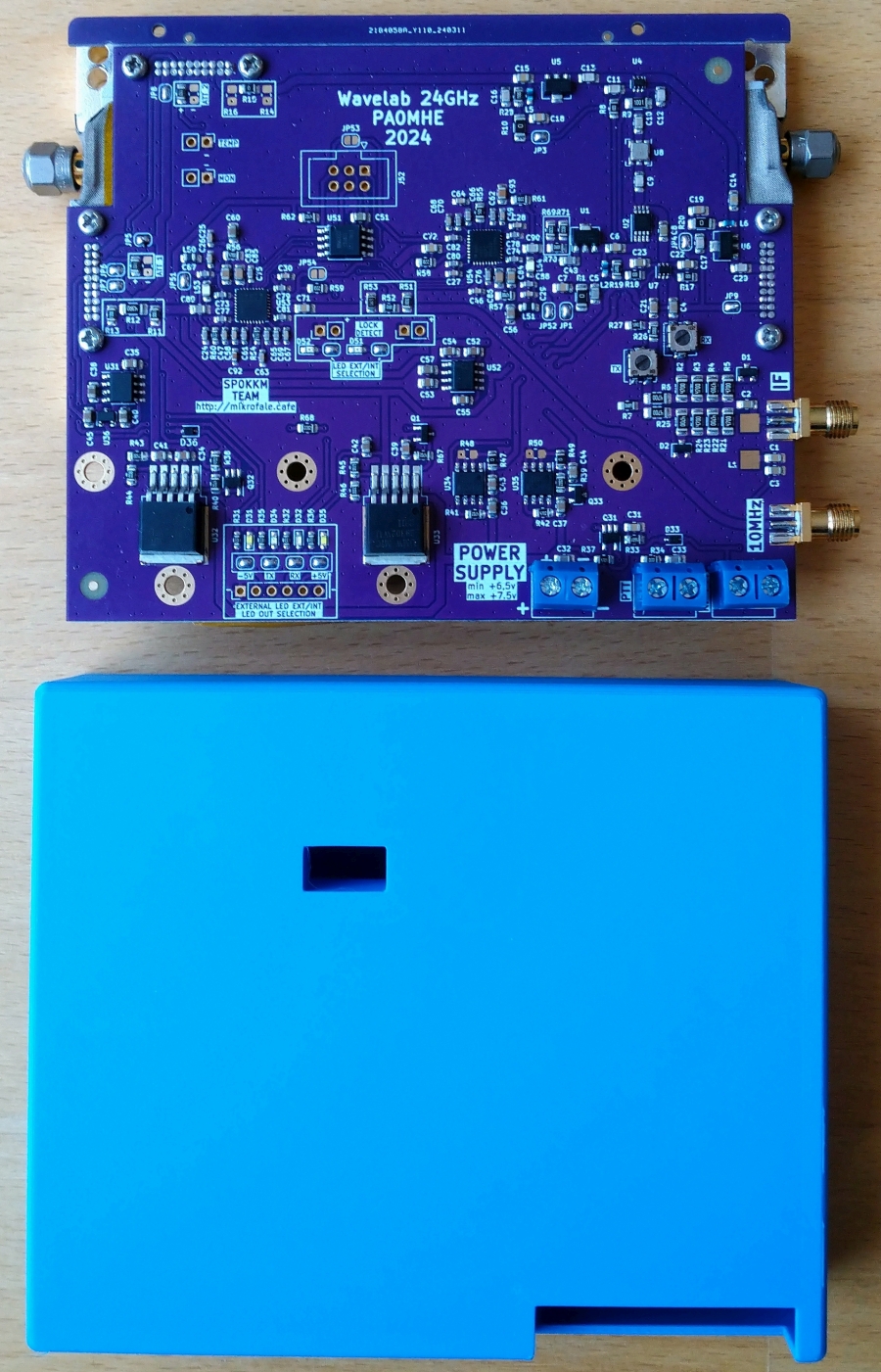
6. PA0MHE wavelab addon PCB
PA0MHE has designed an addon PCB to convert the surplus Wavelab 23 GHz module to 24 GHz ham band.
On Github you will find all information about the Wavelab-24G-Addon-module.
Here is another information by KM5PO about the Wavelab project.
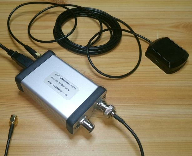
7. GPS disciplined reference oscillator to set 10 MHz reference input
Here I use a nice unit by Leo Bodnar.
It has 2 separate outputs (3.3V CMOS level) from 450 Hz to 800 MHz and it uses GPS reveiver for very stable output frequency.
Output power up to 13.7 dBm
Current consumption @ 12V DC: 190 mA
8. Preamplifier for 24 GHz
I have a DU3T-KLNA.
Noise figure : 1.3 dB
Gain: 30 dB
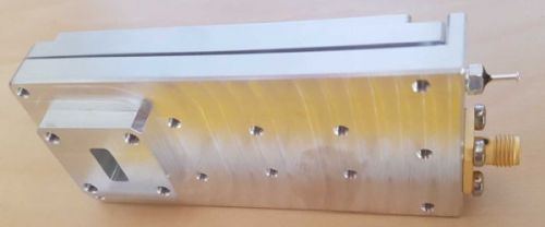
9. Power amplifier for 24 GHz
It is a modified TWT RW1136 by PE1CKK.
Because I use the feedback connection of the waveguide switch I don't need a sequencer.
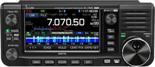
10. IF receiver/transmitter
Therefore I use my modified IC-705 to switch the transverter into TxOut mode.
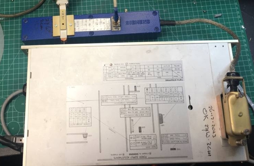
11. Power supply
12. Computer and software
WSJT-X
WSJT-X, developed by Nobel prize winner in physics Joe Taylor K1JT, is an excellent software for weak signal reception.
Mode Q65 is used for 24 GHZ EME and WXJT-X can control my receiver too.
PstRotator
PstRotator works great in combination with my OE5JFL rotor controller. Now I can't only track sun and moon I can track satellites too.
![]()
13. Test results