"MAR104 - Mobile Amateur Rain Radar" Project
Is it possible to make your own (Doppler) Rain Radar? Yes, I think so but nobody did it until yet. It is my target to build a mobile amateur
rain radar for 10.4 GHz under 2000 Euro. 3 cm rain scatter is very similar and OE5VRL (Rudi) gave me some ideas with his 5.7 GHz rain scatter detector
1. Time schedule & status
- March 2010 : Start of project
- June 2010 : Made my radio license
* finished with my call OE2IGL
- Summer 2010 : Finishing system concept and calculations
* finished (see system overview)
- Summer 2010 : Finishing prototype computer and µ-controller software
* first tests with PIC32 and C-compiler finished
* computer software "dBZ calculation" with USB (via RS232) connection finished
* computer software "Radar visualisation" finished
- Spring 2011 : Finishing prototype feed/dish/RSSI & software
* homemade 10.4 GHz feed finished
* prime focus dish mounting on tripod finished
* µ-controller software with high speed ADC (0.5 MSps), USB connection, LCD display finished
* RSSI circuit, impedance converter finished
- Summer 2011 : Finishing of conical feed/dish/receiver without azimuth rotor
* µ-controller software with 12 bit HH-12 encoder, call sign generator
* modified SAT LNB downconverter
* mounting head and rotor concept finished in more detail
- Summer 2012 : Module tests of Rain Radar system with azimuth rotor
* azimuth rotor with worm gear, H-bridge and HH-12 encoder and µ
-controller finished and tested
* power supply (12V accu) finished and tested
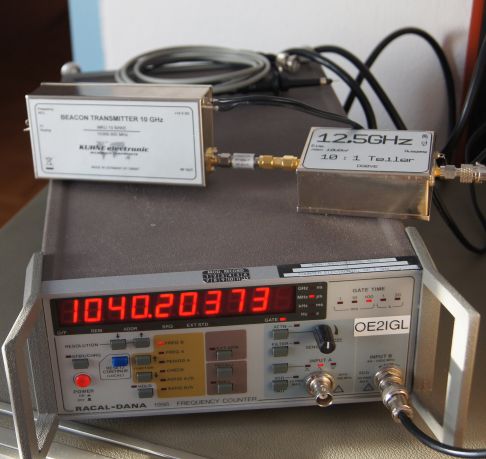
* Kuhne beacon transmitter modified (10.402 GHz and pulsed) and tested
* Receiver, RSSI and µ-controller tested
* Dish/conical feed/LNB at 10.402 GHz tested
- Autumn 2013:
* Test with ready finished downconverter instead of modified LNB
- Spring 2014:
* Optimized feed for offset dish
* Test phase of system (dish-feed-circulator-transmitter-down converter-receiver-RSSI-µcontroller-computer software)
- Autumn 2014:
* System analysis/measurements/improvements
* Upgrade from 220mW to 4W transmitter power
- Summer, autuum 2015 :
* Systemtest with 4W transmitter und tests with mountains
* Some controller pretests/improvements for version 2: use TCP instead of virtual USB, windowing/FFT/filter/IFFT, speed up some code parts
- Planned spring 2016:
* Activation with azimuth rotor
* 1st project target hopefully finished with thunderstorm/rain cells (this radar project is not really a technical issue but spare time consuming)
* Start operation of my Rain Radar with "radar vis" software
Presentation held at
- Skywarn Austria - ZAMG Salzburg (national weather service in Austria) workshop in December 2015
- ZAMG Vienna (headquarter national weather service) in March 2016
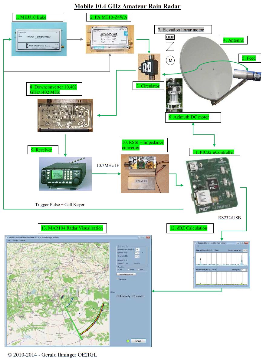
2. System overview
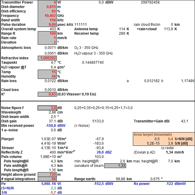
3. Technical details
Frequency :
10.402 GHz, vertical polarisation
Dish diameter :
0.82 m
Dish gain :
37.0 dBi
Effective radiated power : 43 dBi
Dish beam width : 2.5 °
Dish rotation : 1 per minute
Azimuth resolution : 0.9 eg;
Time per azimuth step : 140 msec
Echo time :
2 msec
Pulse :
9 µsec
Pulse repetition freq. : 500 Hz
Pulse integration : 60 x
Distance minimum : 1.5 km
Distance maximum : 100 km
Distance resolution : 1500 m
Sensitivity :
1.5 mm/h at 100 km
Power consumption 12V : 36 W
Weight without accu : 25 kg
Costs :
1500 ? (more homemade and used parts < 1000?)
4. Details of used modules
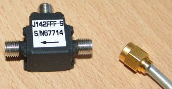
10.2 - 10.8 GHz circulator
- Isolation: 30 dB
- VSWR: 1.12
- Insertion loss: 0.35 dB
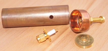
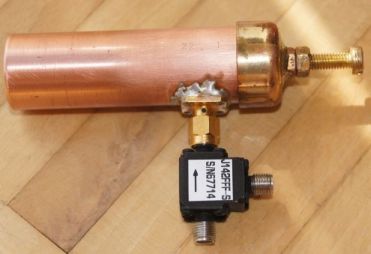
Homemade 10.4 GHz conical feed (wave guide)
- Copper tube with inner diameter D: 20.1 mm
- VSWR adjustment by moveable back wall
- Wave guide formula:
1 / Lamda02 = 1 / Lamdac2 +
1 / Lamdag2
Lamdac
= 1.706 x D = 34.3 mm
Lamda0
= 28.82 mm (10.402 GHz)
-> Lamdag = 53.2 mm
- Wave guide drawing:
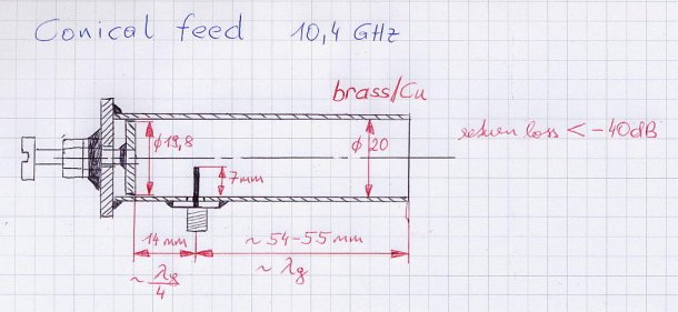
I use this feed to transmit and receive signals in combination with a circulator. Therefore return loss must
be as low as possible (< -30dB). After first measurements of return loss and adjusting back wall with the screw I got around -20dB. Then I adjusted
the length from the open end to the pin to 54mm (1x Lamdag). Now the return loss is better than -40dB.
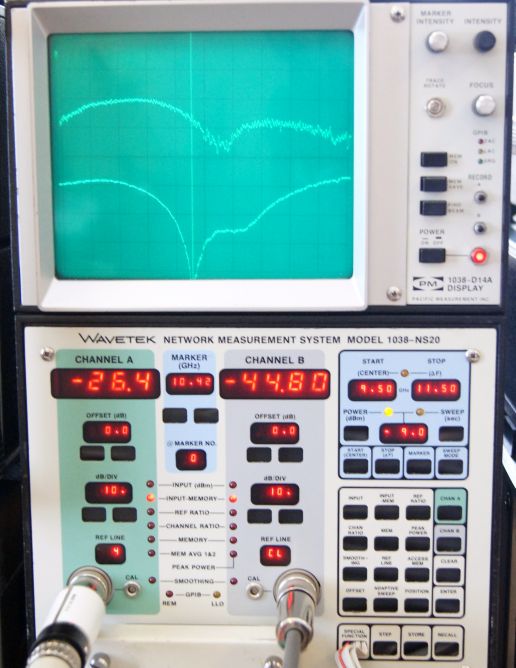
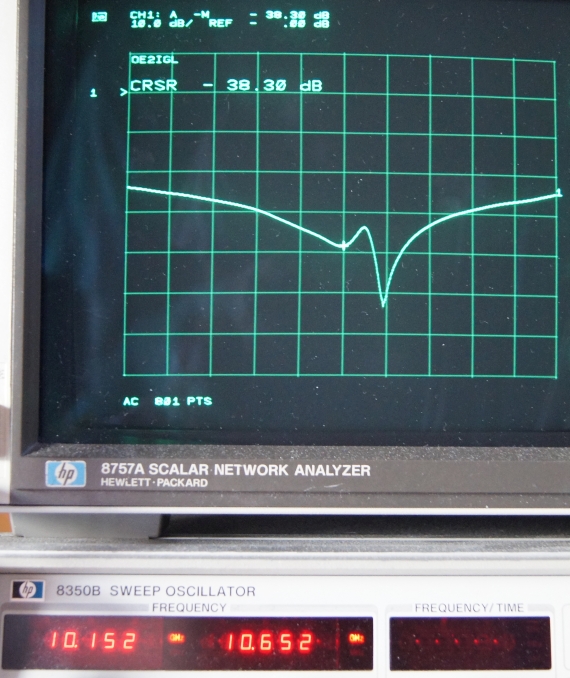
Return loss of 45 dB (lower curve) @ 10.42 GHz, >42 dB @ 10.402 GHz
- For prime focus dish with f / D = 0.36
Closed end has a moveable back wall to adjust return loss.
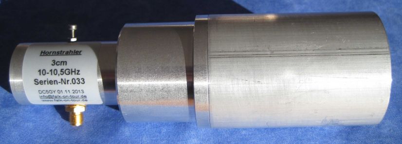
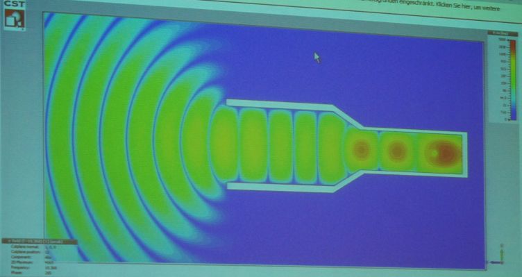
- Optimized dual mode horn feed for standard offset dish with f / D = 0.67
Now this dual mode horn is my standard feed. Johannes Falk DC5GY has simulated this feed with CST microwave for best performance
and measurements confirm his simulations.
It is robust, easy to adjust for best matching (with M2 screw), fits into standard LNB holder and is optimized for offset dish. Return loss is around -38 dB and should be enough
that TX pulse (4.4 W) is below 1mW at RX input.
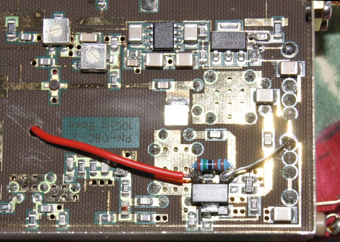
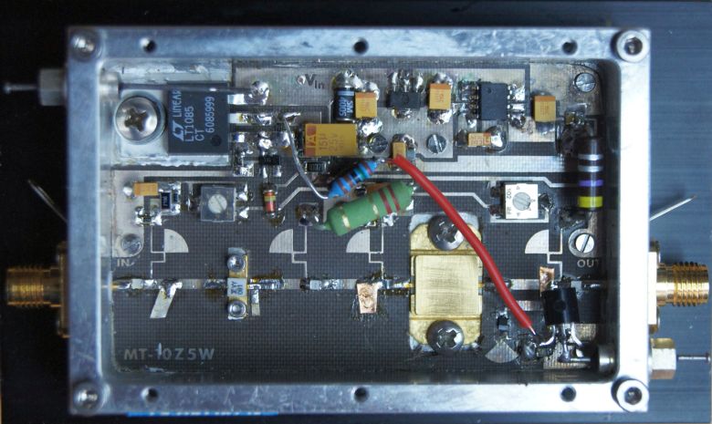
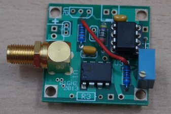
10.402 GHZ microwave transmitter
This is the original Kuhne 10.368 GHz beacon transmitter
with approx. 220mW.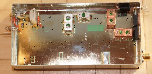
As this transmitter has only F1 (frequency) modulation I looked for simple A1 (amplitude) solution to switch on/off my pulse
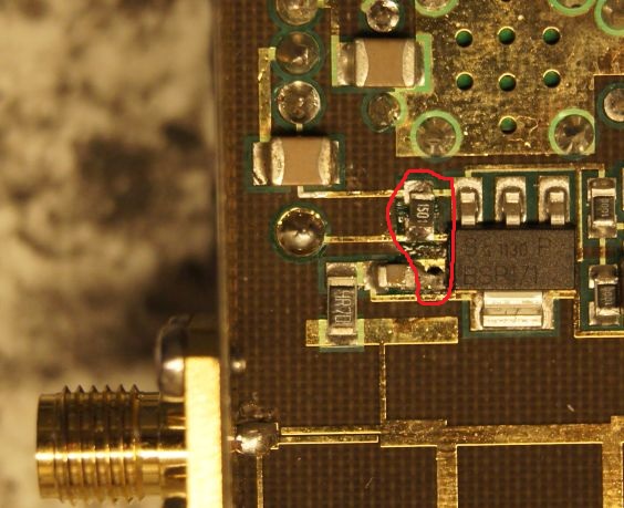
radar. To my surprise I found a p-MOSFET transistor (4 pin IC on the left above the output stage) doing this on the board. After little changes (see
red marked area) and an additional n-MOSFET transistor it is possible to use F1 input as A1 input.
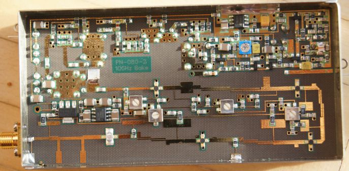
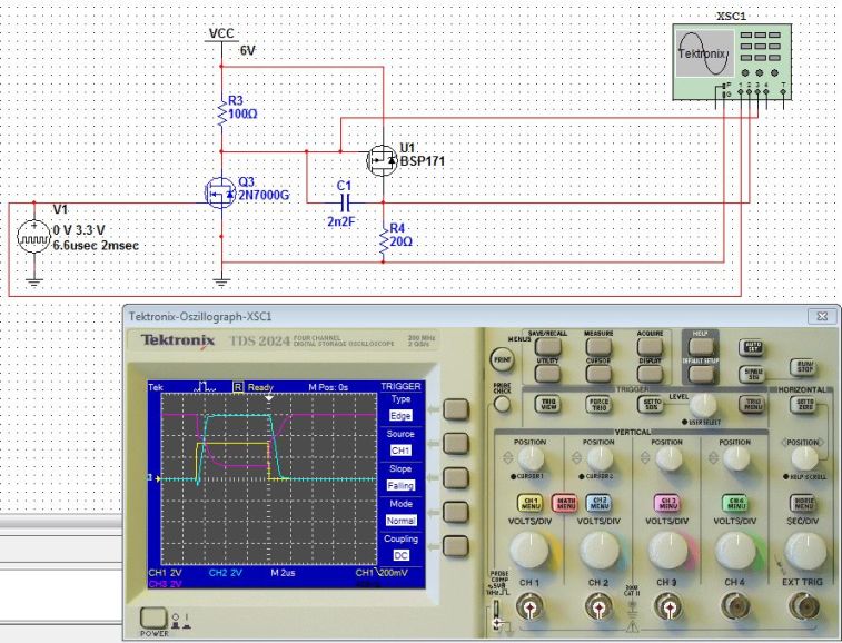
In addition last transistor multiplier stage (before power amplifier stage) also has such a n-channel/p-channel combination to switch
transistor power. Otherwise you will see a small signal from oscillator stage during pulse off periode at the 10.4Ghz output. Don't switch off/on
oscillator stage!
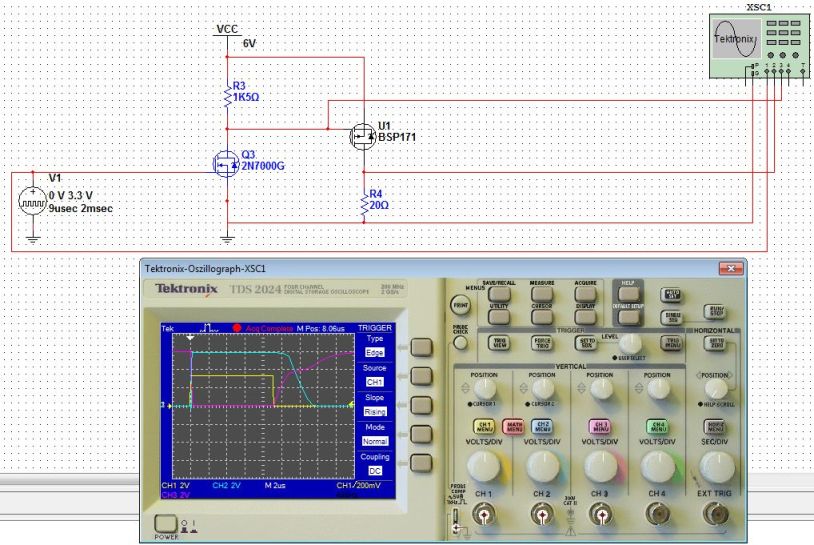
Here is a Multisim simulation and the real oscilloscope image. Yellow line = µcontroller pulse, blue line = TX pulse (power
supply of amplifier).
Switch off edge of p-MOSFET is delayed and not sharp-edged. This could be adjusted with R3.
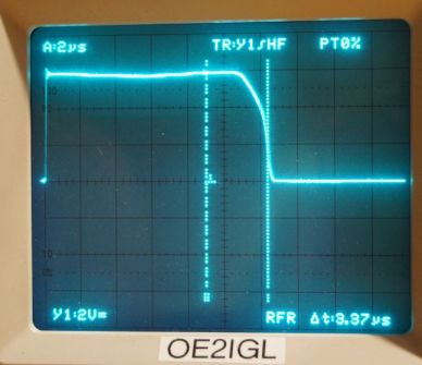
Improved version: better pulse shaping of output pulse (blue signal), rounded rise and fall edges.
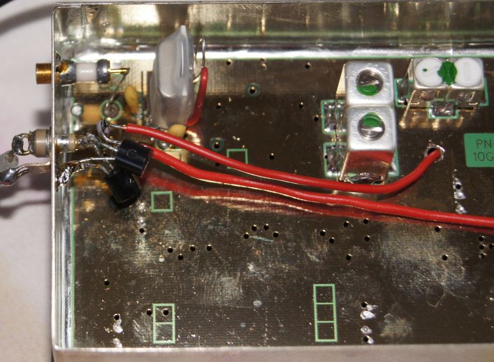
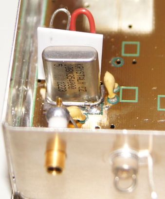
Instead of the original 108.009 MHz quartz crystal I use a 108.354 MHz quartz crystal by Krystaly in Czech (thanks to OE5VRL for organizing). I only had
to adjust the oscillator and then the output shows 10.402 GHz with 250 mW. Behind the quartz you can see the little quartz heater board.
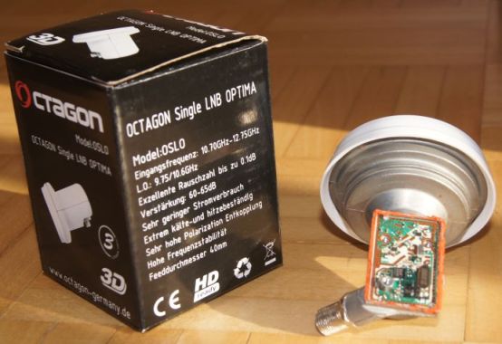
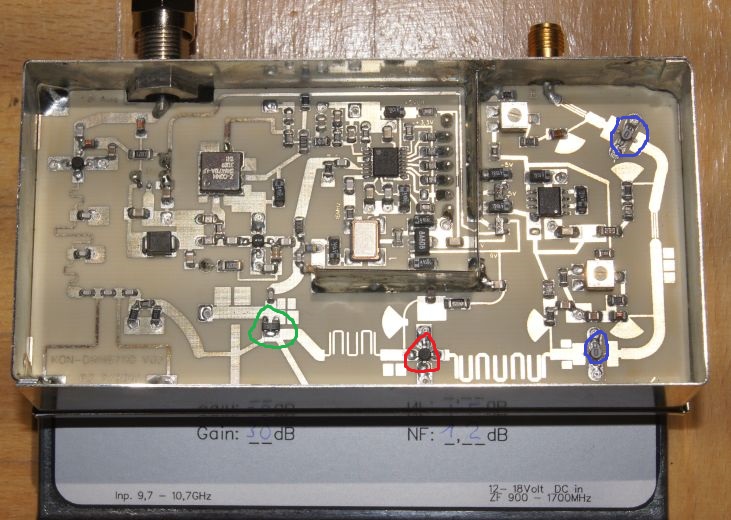
Downconverter 10.402 GHz -> 652 MHz/1402 MHz
Some microwavers made good experiences with standard satellite LNB's. They have low noise
figure, high gain and are very cheap. My first tests were done with such a modified LNB.
In March 2013 I found first LNB with a PLL instead
of a resonator pill. Stability of frequency is much better with a PLL.
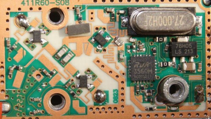
The internal 27 MHz quartz is multiplied by 361.111 inside the RD3560M chip to get L.O. of 9750 MHz and I.F. of 652 MHz.
Big disadvantage of all modified LNBs is a poor noise figure at 10.4 GHz. Bigger than 2.8 dB against 0.55 dB at 11.5 GHz, measured with cold sky - hot sun method.
See more about modified LNBs here.
Here is my current downconverter and a noise figure of 1.2 dB is doable. Roberto
Zech DG0VE has good converters, e.g. the KON-DWN 97107. L.O. is 9000 MHz and I.F. is 1402 MHz.
As I will not switch off the downconverter/receiver stage during Tx pulse the
downconverter detects the reflected Tx pulse of the feed horn.
3 amplifiers in front of the mixer are good for my weak echo signal but gain is too high
for my strong dircet Tx pulse signal. Therefore I removed the 3rd amplifier (red one) to reduce overload of mixer.
green = sub-harmonic diode mixer
red = amplifier
blue = low noise amplifier
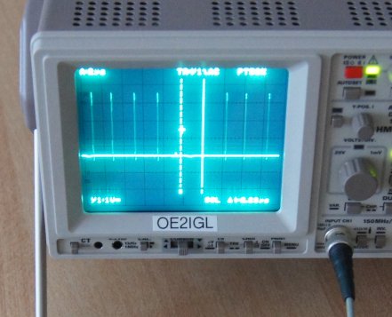
Received pulse spectrum after down converter with 18µsec Tx pulses.
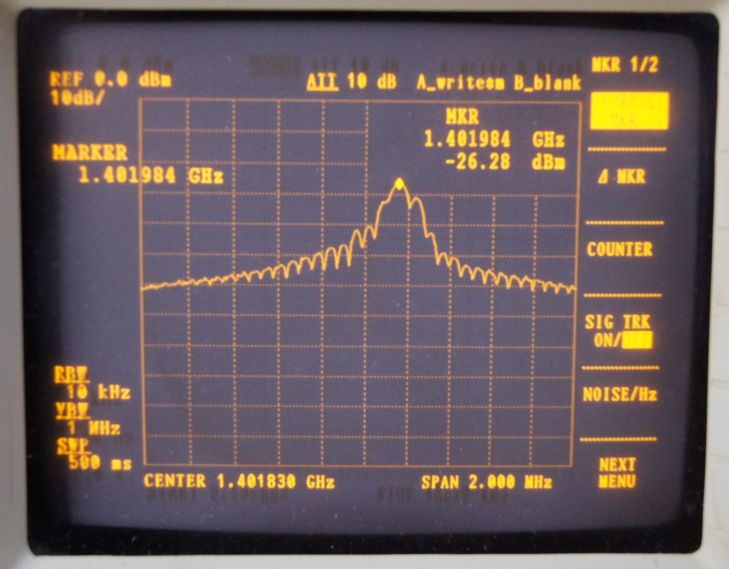
Echo signal against cold sky (no cloud, no rain, no hindrance). Peak is reflected Tx pulse from horn feed (first 20µsec) and after 20µsec there
is only noise.
vertical -> signal strength of echo
horizontal -> time/distance
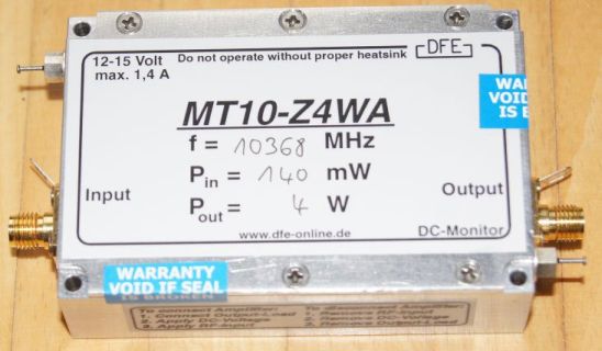
Power amplifier
To get more Tx power I use a 10.4 GHz PA made by Dirk Fischer DK2FD with max. 4.4 W output (Pin = 200mW). That gives additional
13 dB output power.
PA is switched on/off with same n-channel/p-channel combination as used in beacon transmitter (switching drain power of amplifier).
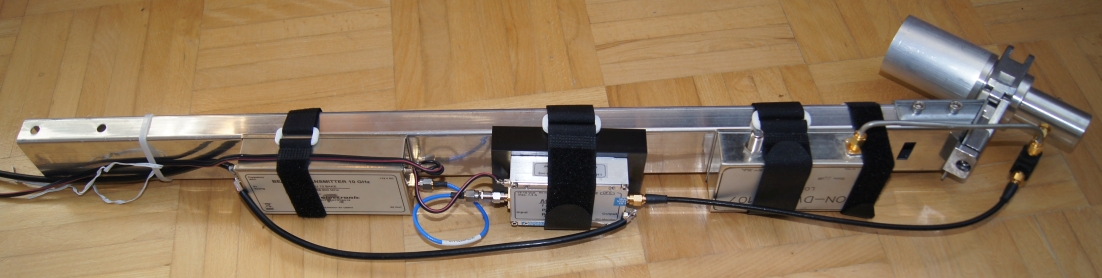
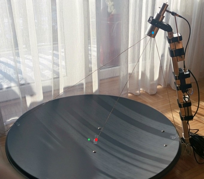
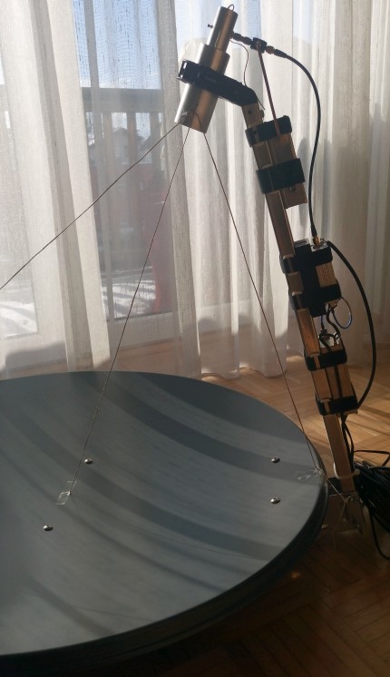
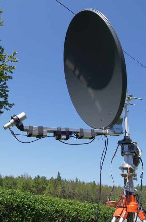
Final Tx/Rx combination
Feed arm with dual mode horn - beacon transmitter - power amplifier - circulator - downconverter.
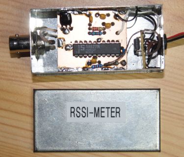
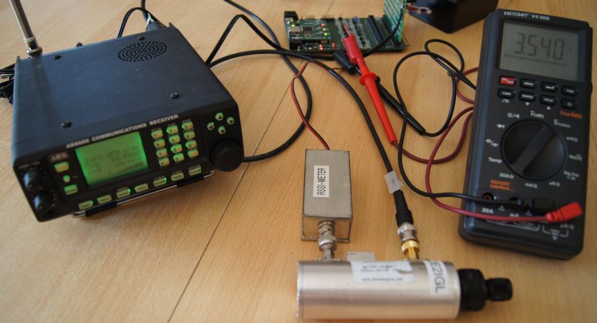
AR8600 scanner with 10.7 MHz I.F. output and external RSSI (logarithmic received signal strength indicator)
A RSSI can be built with e.g. SA627 and buffer amplifier to drive A/D of µ-controller. SA627 has a fast rise and fall time
of 1-2µsec and a RSSI range of 90dB.
RSSI (mV) of SA627 chip versus RF input (dBmW) and AD8307 power detector (red curve)..
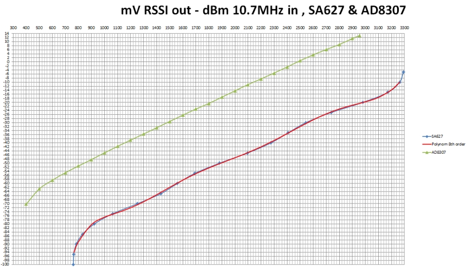
Next improvement is a better power detector with AD8307 and matched 10.7 MHz filter. Fall/rise time is shorter than 500 nsec.
AD8307 has a very linear output curve between -60 and +15 dBm, 33 mV/dB with a gain of 1.47 (green curve).
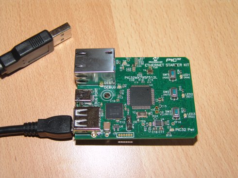
PIC32MX µController
I use a PIC32 USB starter kit. This controller has a speed of 80 MHz. As I also have a PIC32 Ethernet starter kit it is possible to use an ethernet
connection between µcontroller and computer (instead of USB connection).
USB starter kit tests with I/O expansion board and LCD/4x4 keypad
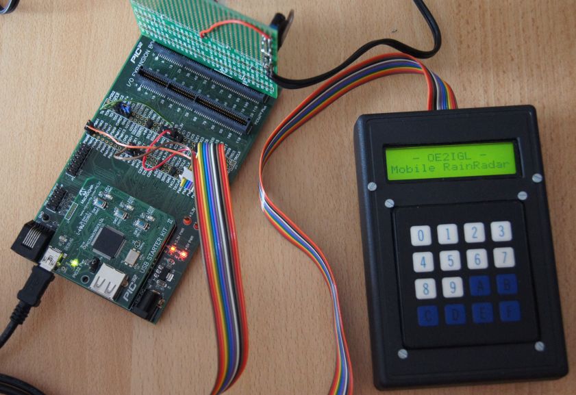
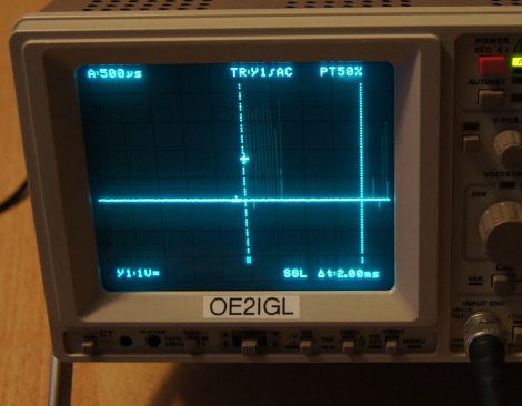
Sampling pulses every 2.22µsec and echo time up to 2ms
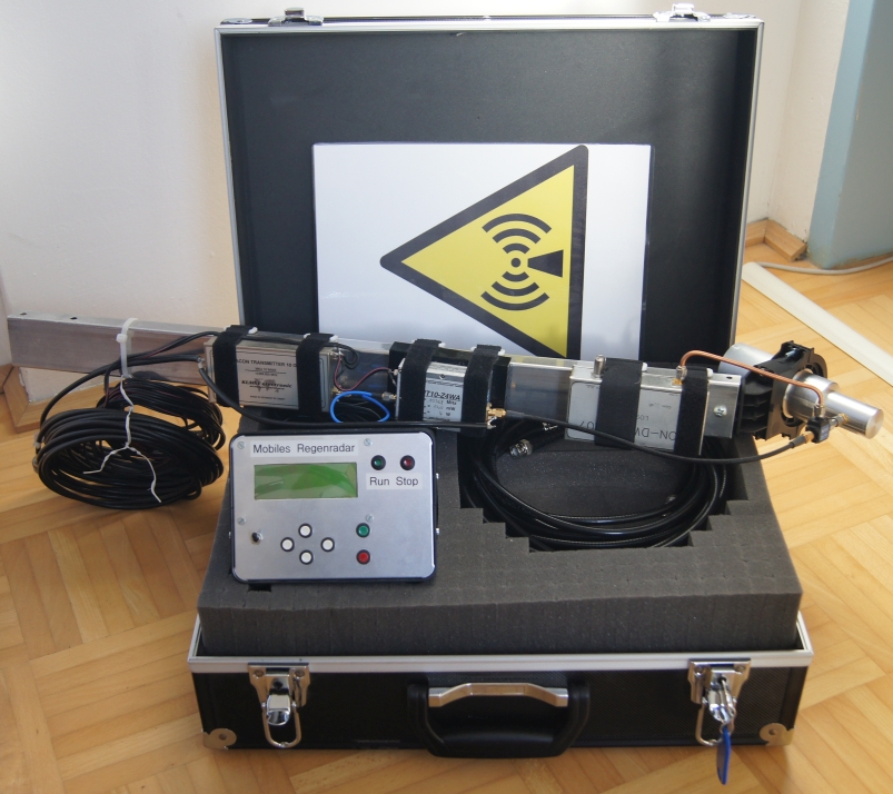
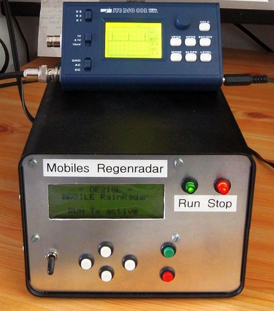
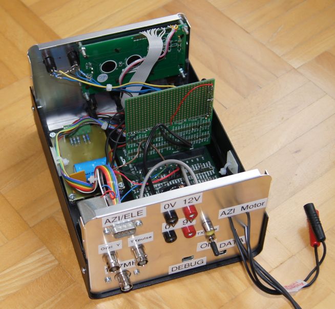
µ-controller, RSSI meter, LCD, push buttons, motor driver in one box.
Pulses every 2ms in Tx mode.
Offset dish
I only use Gibertini offset dishes, in this case model OP 85 L (870 x 815 mm, f/D = 0.67, dish illimination 70°).
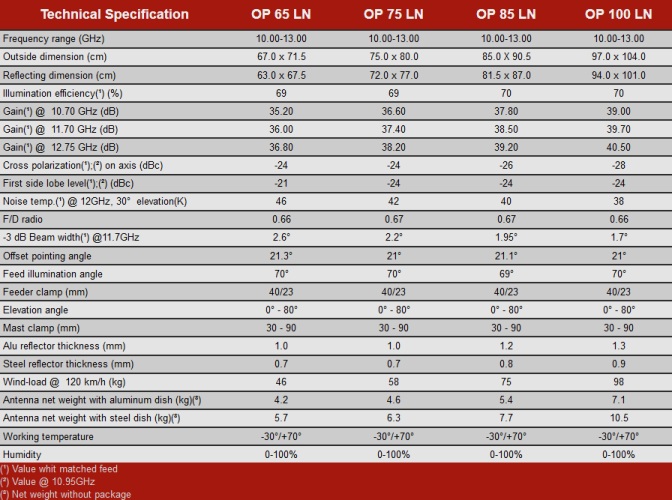
At first I tried to find deepest point of offset dish along long axis. In my case the depth is 68.5 mm
f = shortaxis³ / 16 / longaxis / depth = 813³ / 16 / 870 / 68.5 = 564 mm ... distance from focal point (blue) to bottom rim of
offset dish
offset tilt = arccos (shortaxis / longaxis) = arccos (813 / 870) = 20.9°
To determine the position of focal point I use hdl_ant software by W1GHZ.
Input is long and short axis, max. depth and distance from max. depth to bottom rim.
Output is the distance from focal point to top rim and distance from focal point to bottom rim.
Then I made a knot into a string and measure both output distances from the knot to both ends.
I fixed both marked ends on the dish (bottom and top rim) and then the knot showed me the focal point (blue point).
I got best signal if the focal point is approx. 20-30 mm inside the dual mode feed or 30 mm in front of feed holder. Difference between phase center of dual mode feed
horn and focal point must be smaller than wavelength/4, in this case better than 7 mm.
To get a very sharp focal point the dish geometry (deviation from parabolic shape) must be better than wavelength/4.
blue point ... focal point of dish
green point ... center of dish
red point ... deepest point of offset dish
For best illumination of an offset dish the feed should point to the deepest point of the dish. That's not the center of an offset dish!
Again I used a string from the deepest point to the focal point. The string and the feed axis are parallel -> perfect!
Mounting head for azimuth and elevation
First tests with a small dish and motor controller in 2011.
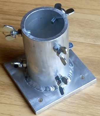
Aluminium tripod adapter.
Finished azimuth rotor with elevation sensor (small black box), azimuth encoder and tripod.
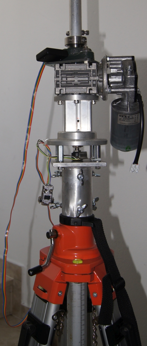
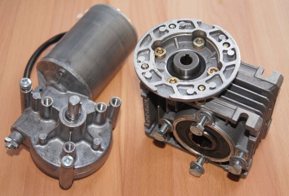
DC motor with encoder for azimuth (0 to 360° degrees)
12V (5A, 5Nm, 40 rpm) worm gear motor with additional worm gear (20:1) to get 2 rpm.
Torque is approx. 100 Nm.
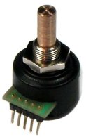
HH-12 Encoder has a resolution of 12 bit and an accuracy of approx. 0.2°.
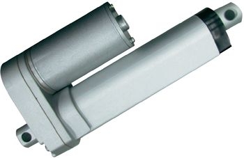
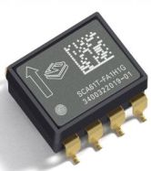
DC linear motor for elevation (0 to 90° degrees)
Not yet installed but I use the inclinometer sensor SCA61T.
5. Computer software
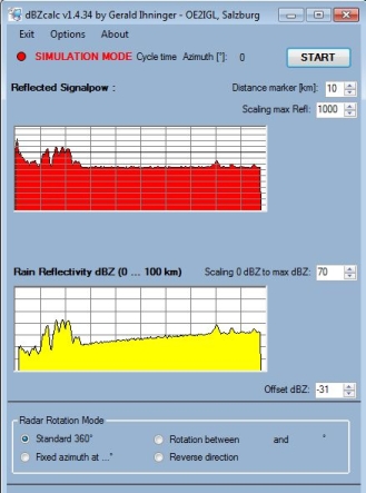
"dBZcalc v1" is a VB.net software running under Windows OS. It is connected to the µ-controller via USB cable (virtual COM port, RS232) and transfers echo data from the RSSI analog-to-digital 10bit converter to the computer. These data are buffered in a file and the second VB.net software called "MobileRadar" reads this file.
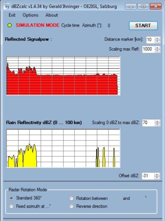
Upper chart shows reflected echo power (dBWatt) coming from power detector and lower chart shows calculated dBZ from echo power.
Right screenshot shows dBZ chart with activated noise floor eliminator.
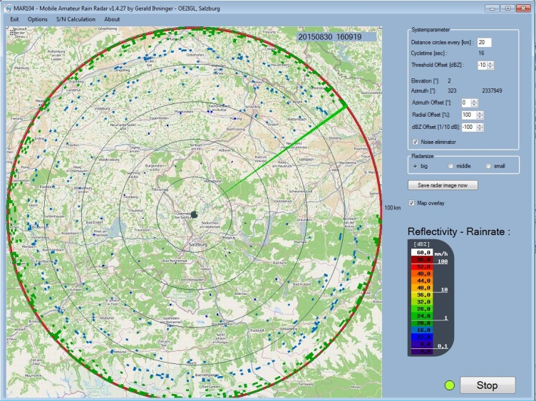
"MobileRadar v1" is a VB.net software running under Windows OS and reads data from a file created by "dBZcalc". "MobileRadar" also converts echo data into dBZ values representing rain rate [mm/h] and makes a rain rate overlay.
Some rain areas
image coming soon
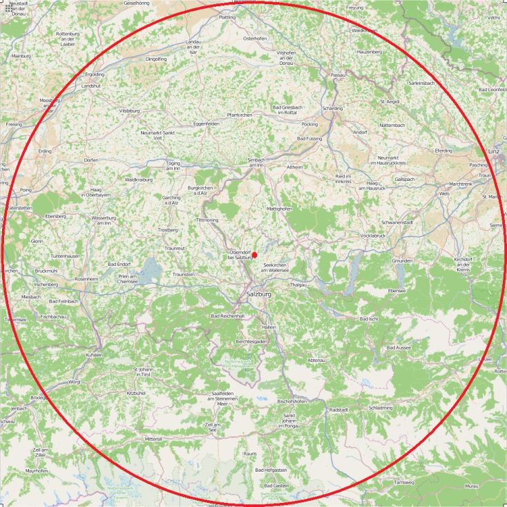
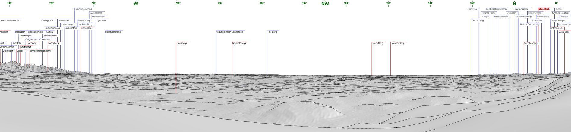
6. Place of test/operation
The red area shows visual range of the rain radar from "Haunsberg" (730m), 47.936N, 13.014E
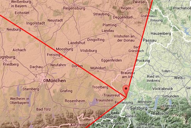
Red point shows the location of the station and the red circle shows the range of 100 km (up to Linz and Munich).
 ©
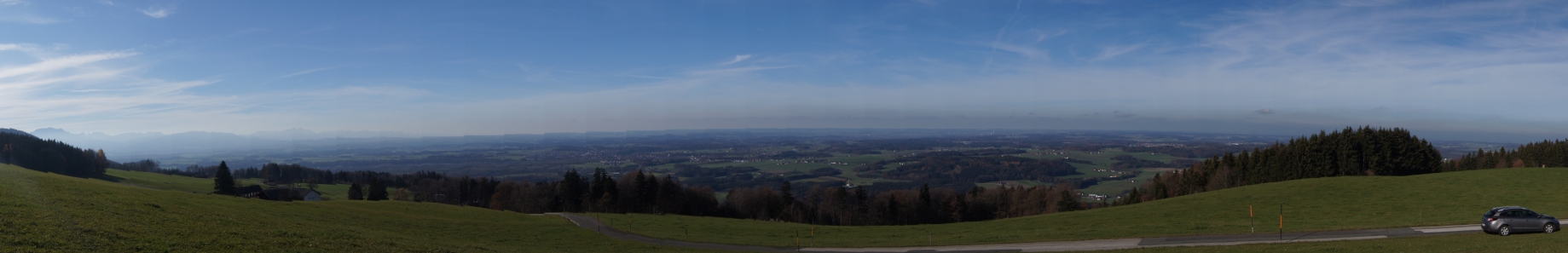
Panorama http://www.udeuschle.de
©
Panorama http://www.udeuschle.de
7. Tests and results
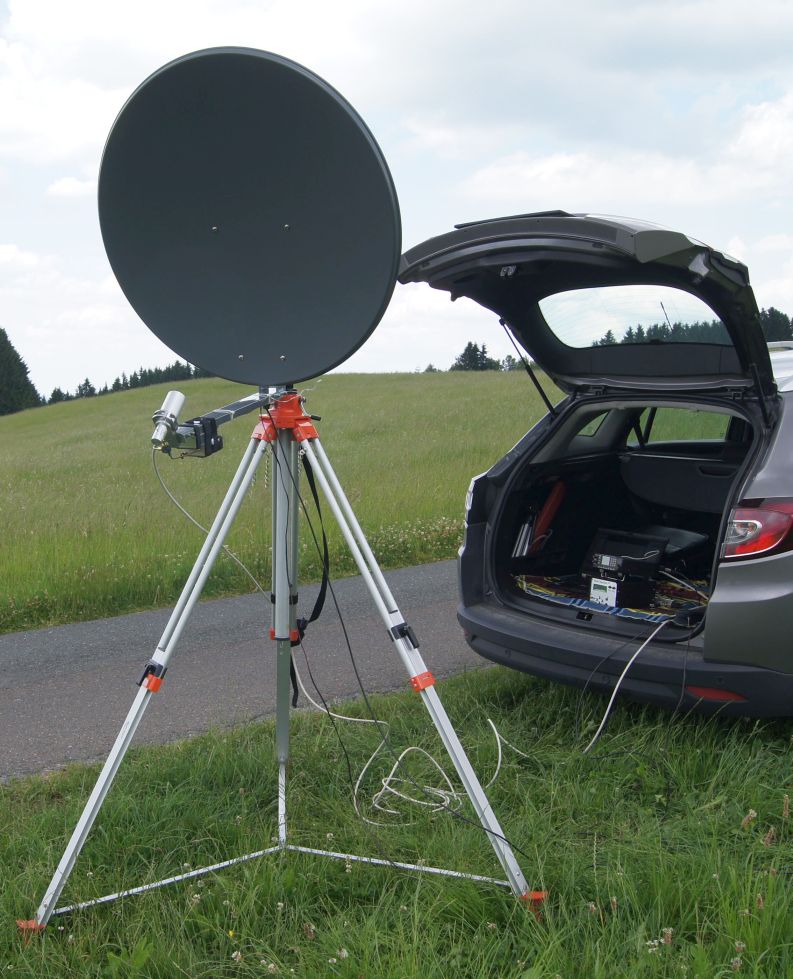
This was my FIRST TEST of the pulse radar equipment in June 2014. First test was made without azimuth rotor. 20µsec pulsed transmitter, receiver
and software are working but the system needs some improvements for best performance.
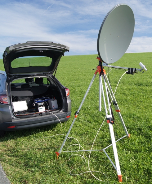
I use this tripod also for noise measurements (hot sun -
cold sky method). This tripod can be extended to a top height of almost 3m without azimuth rotor system, 3.5m with it.
Adjustable cross-ties give better stability.
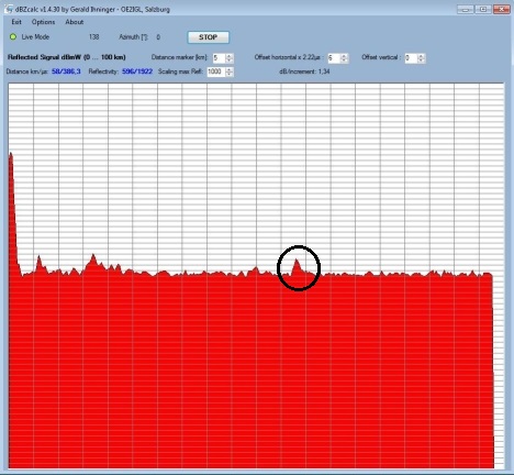
My SECOND OUTDOOR TEST in October 2014 showed much better results (with reduced down converter gain and additional power switching of last transmitter multiplier
stage).
Now I use a 9µsec transmitter pulse and 60 times averaging of weak reflected signal (230mW beacon transmitter power without PA).
First large
peak is Tx pulse coming back to receiver and the next peak comes from mountain echos (distance around 20km).
vertical -> signal strength
of echo
horizontal -> time/distance

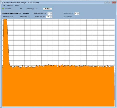
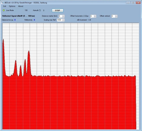
THIRD OUTDOOR TEST with 9µsec pulses, 60 times averaging and only 230 mW transmitter in October 2014. This time I removed a 20dB external attenuator
in front of the RX because I don't need it. This enhanced signal-to-noise value.
Echos obtained from mountains, 0.5° to 2° degrees above
horizon. Now system performance is very good (also without Tx PA) and next tests with rain clouds are planned.
In this case hindrance distance
is 2.7 km and minimum distance is limited to 1.5 km because of TX pulse width (10µsec * 3E8 m/s / 2 = 1500 m).
Distance range is
from 0 to 100km (left to right).
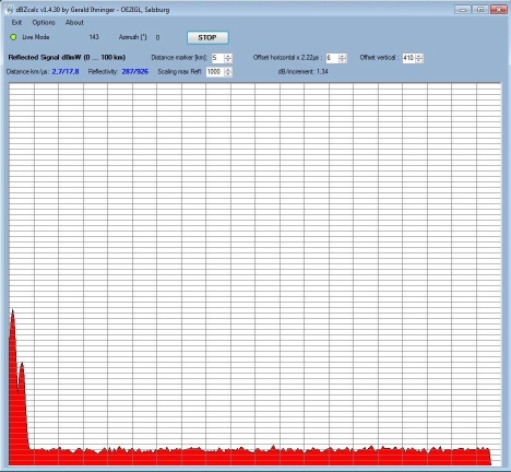
Hindrance at 58.0 km with 3dB (S+N)/N.
Strong multiple echos between 10 and 20 km with up to 23dB (S+N)/N.
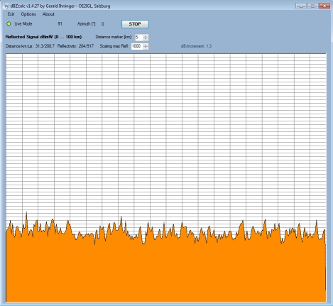
Why 60x signal averaging? -> to improve S/N by 10*log10(number of samples)0.5 , factor 0.5 is worst case, normally between 0.5 and <1.0
Approximately:
S increases by factor #samples. N = sigma
increases by factor (#samples)0.5 because (sigma)² (= variance) is additive.
1-sigma of noise is
(4.3 / #samples0.5) dB. To detect a signal S it should be 4 times greater than 1-sigma of noise.
As I only use an incoherent integrator after detector (video integrator) S/N improvement is smaller than with coherent integrator in
front of detector.
This video integrator smooths the noise and so it is easier to detect a low signal.
Only 1x sampling for comparison. Noise fluctuation
is much higher than above and it is not possible to detect a very small
signal.
4th OUTDOOR TEST with 4 Watt power amplifier was in July 2015. Everything was working with 12-13 dB more power and 20 km echo grows up to 35 dB (S+N)/N.
This time I was able to detect mountains at a distance of 95 km with 5.5 dB (S+N)/N and this level matched with my "scatter budget calculation
for area targets".
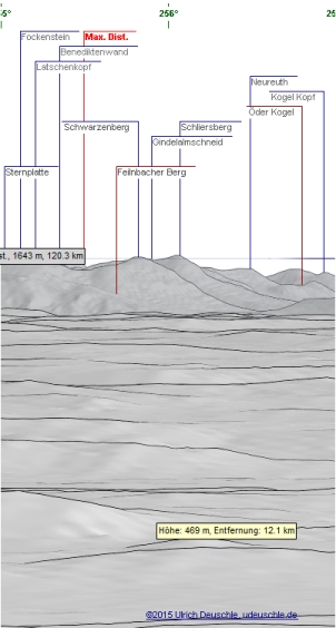
Here is a nice example of ground clutter combined with mountains.
Mountains are marked in red:
- 78/80 km with Felnbacher Berg and Schwarzenberg
- 87 km with Schliersberg
- 95 km with Neureuth
The right image shows simulation from my view point and it corresponds to dish beam half angle.
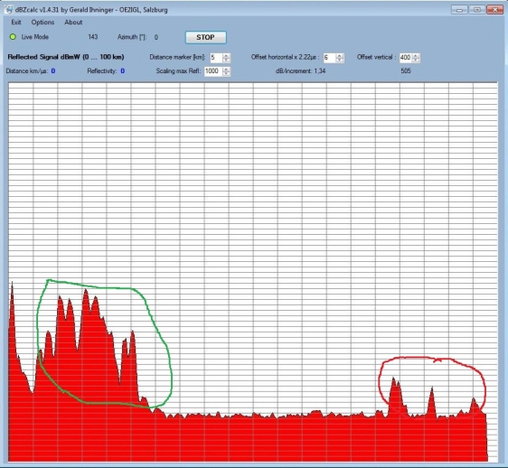
Ground clutter is marked in green between 5 to 25 km and is located in front of the mountains.
Between 25 and 80 km there is only noise because ground
area can't be seen.
Beam half angle is marked in black.
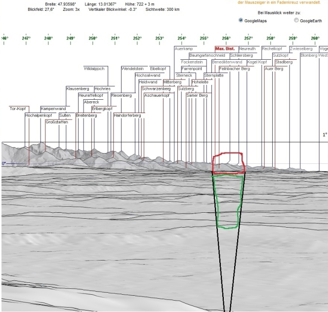
©
Panorama http://www.udeuschle.de
5th OUTDOOR TEST with 4 Watt power amplifier and following improvementswas in August 2015:
-
AD8307 power detector (RSSI) test with calibrated RFin [dBm] - Output [mV]
-
Mouse pointer shows dBm in echo power chart in dBZcalc.exe
-
dBZcalc.exe shows dBZ chart
- Archiving of echo
power data with simulation/playback mode (reuse of archived echo power data in
dBZcalc.exe) is active
- collect a lot of archiving
data for playback tests
- make some closing
test (noise at different elevations, noise averaging, puls length, different
coax cables, ...)
6th OUTDOOR TEST with azimuth rotor and fixed
elevation in fall 2017 :
Now it is time to detect thunderstorms and rain
.... STAY TUNED!