From James Clerk Maxwell to rectangular/circular waveguides and cylindrical cavity filter
This is an excursion into history of amateur radio, electromagnetic radiation, waveguides and their applications like microwave cavity resonators.
1. James Clerk Maxwell and his equations

J.C. Maxwell (13 June 1831 - 5 November 1879) was a Scottish scientist in the field of mathematical physics. He formulated the classical theory of electricity, magnetism and electromagnetic radiation.
In 1865 Maxwell demonstrated that electric and magnetic fields travel through space as waves moving at the speed of light.
His famous twenty equations, in their modern form of four partial differential equations, first appeared in 1873. Because of his prepared work other scientists, like Heinrich Hertz, Guglielmo Marconi
were able to develop the radio technology.
Find more in detail about his life in Wikipedia.

Source: Wikipedia
Maxwell's equations:
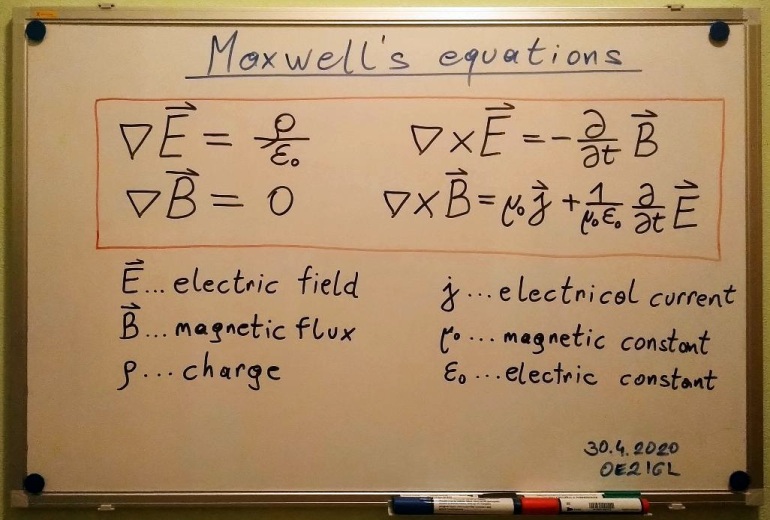
2. Solving this equations
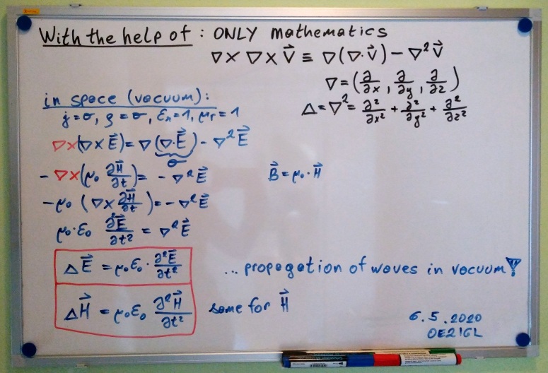
Now we are looking for solutions for E and H ~ B that meet the equations.
At first we will show that Maxwell's equations can predict an electromagnetic radiation.
Then we will see that following solutions meet the condition: a plane wave travelling in z-direction with the speed of light

3. Rectangular waveguide
Now we use same way to find solutions for special applications. In this case for an electromagnetic wave travelling through a rectangular waveguide.
In addition we need some boundary conditions because the wave isn't free in all 3 directions. I will skip these steps because it is some mathematics.
If you are interested then have a look on the internet or books4.
Only if the frequency f is greater than cutoff frequency fc we have propagation in a waveguide. Therefore a waveguide acts as a high pass filter.
ATTENTION: small typo in image below. Dominant mode is TE10 (not TE01 !!!) with fc,10.

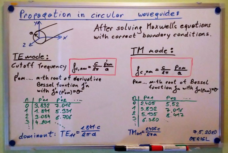
4. Circular waveguide
Now the same method for a circular waveguide. It is a lot more difficult because we need the Bessel function.
Again, if you are interested then have a look on the internet or books4.
5. Linear polarisation of waveguides

6. Rectangular microwave cavity resonator
The Maxwell's equations can also be used to calculate a rectangular microwave cavity filter. Although the waveguide and cavity resonator have been investigated theoretically since the end of the 19th century and experimental attempts were made in the 1930s-1940s, there is little information about them.
7. Cylindrical microwave cavity resonator OE9PMJ (Peter Riml)
As a circular waveguide has less loss the quality factor Q is higher. Therefore the cylindrical cavity filter is more common.
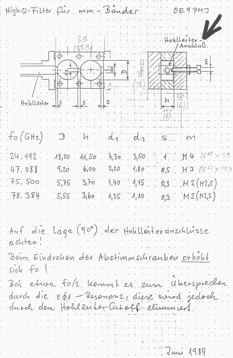
In 1989 Peter Riml OE9PMJ (SK) wrote notes of this cavity filter on a piece of paper.
In 1992 this sheet was published in the conference proceedings of the ham radio conference in Munich2. No further details are available, only this one page!
Since then this cavity filter is widely used for microwave transverters.
In 2017 Paul Wade1 W1GHz published some simulations for better understanding of this type of filter. He built filters and then he made measurements for comparisons.
He could also explain the filter behaviour after changing dimensions. A great help for the adjustment of the filter.
I try to give more insight into the calculation of such a cavity filter.
Some theory behind the cylindrical waveguide resonator:
It is similar to a circular waveguide. Again we have to solve Maxwell's equations with boundary conditions. But in this case the wave is restricted in all 3 dimensions.
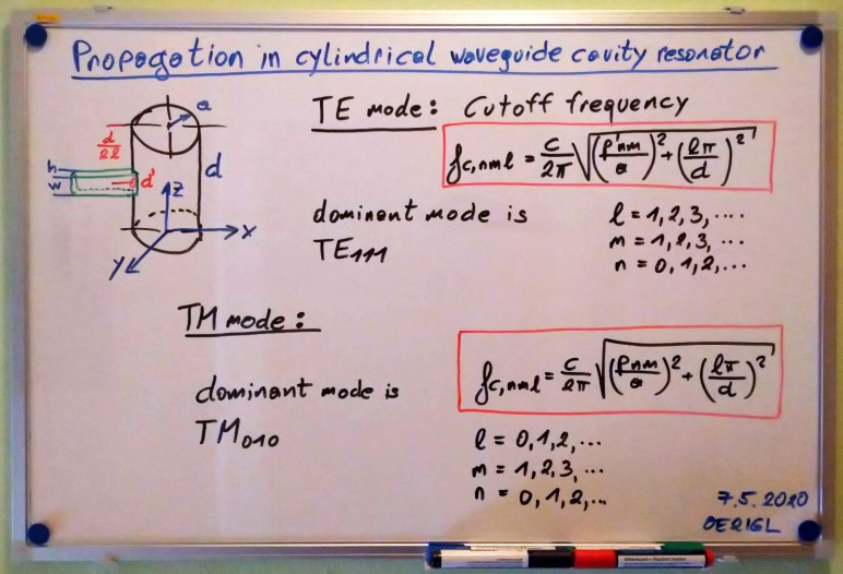
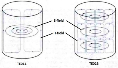
TE011 and TE023 mode in a cavity resonator7. As the E-field doesn't touch the walls the quality factor Q is mucher higher than for the dominant TE111 mode.
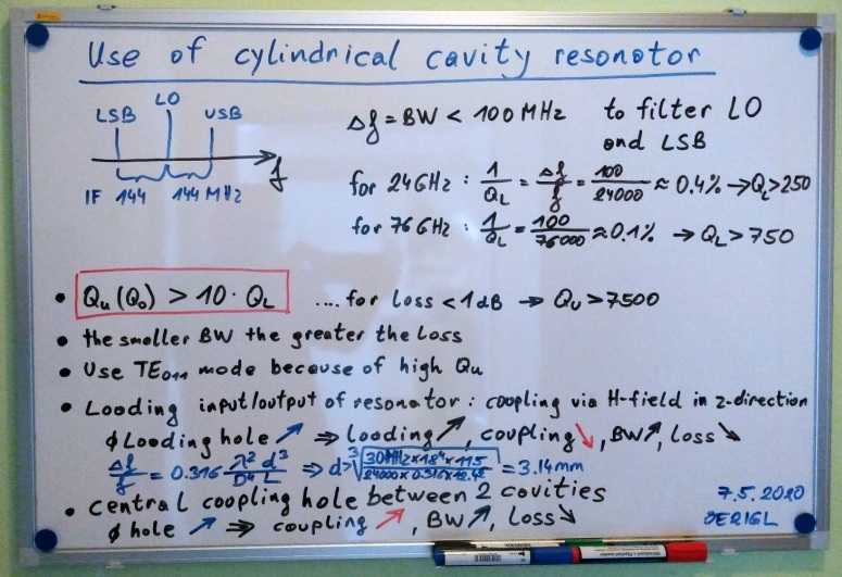
Coupling into the resonator could be done via waveguide through a coupling hole with diameter d'. d' could be found below with formula 1A type by I.G. Wilson3.
Choose desired bandwith and calculate d'. Be careful, different height and diameter characters are used here!

Quality factor Q:

Unloaded quality factor as a function of diameter to length ratio for TE0mn mode3. Be careful, different mode indices, height and diameter characters are used here!
TE023 mode has a very high quality factor but the cavity is much bigger than for other modes. Formula for unloaded Q could be found in "Microwave Engineering"4.

Unloaded quality factor as a function of diameter to length ratio for TElmn mode3. Be careful, different mode indices, height and diameter characters are used here!

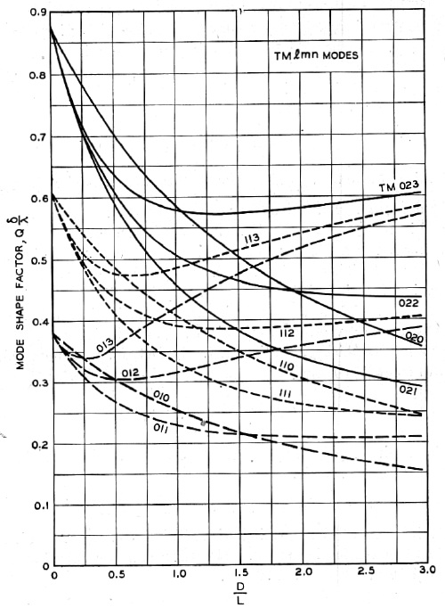
Unloaded quality factor as a function of diameter to length ratio for TMlmn mode3. Be careful, different mode indices, height and diameter characters are used here!
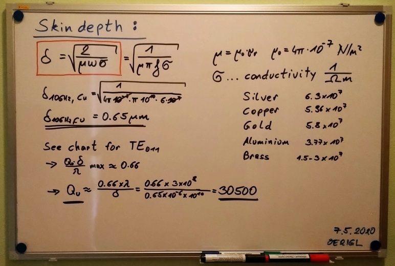
To get the unloaded quality factor from the charts above we need to know the skin depth. Here is a summary to calculate the skin depth for different materials and frequencies.
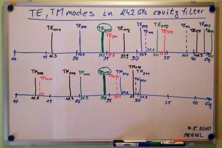
OE9PMJ cavity filter dimensions, TE/TM modes and quality factor for 24 GHz:
Some general parameters are shown her for the double cavity filter. It is an addition to the brilliant DUBUS article1 written by W1GHZ.
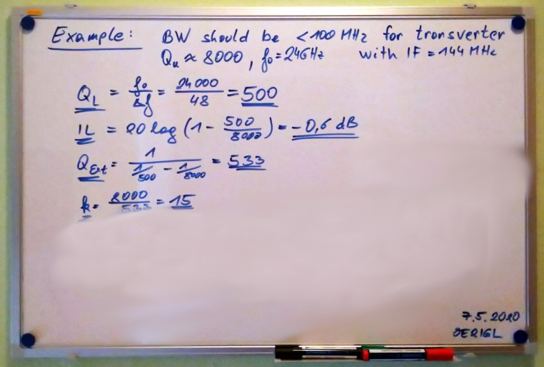
As example I calculate a 24 GHz cavity filter with IF of 144 GHz and TE011 mode.
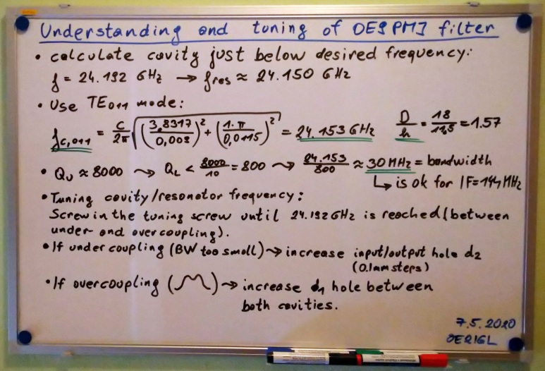
For the input/output coupling hole I use the formula shown above. The diameter is an estimation and it is underestimated but a good starting point.
As the wall thickness of the cavity is not zero add the thickness to the diameter. In our case 1 mm wall thickness + 3.14 mm = 4.14 mm. Use a diameter between 4.2 to 4.4 mm
to get a critical coupling.
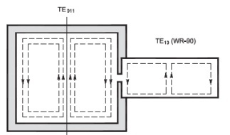
Here you can see that TE311 mode is very near to our TE011 mode at 24.1 GHz. With the screw on top of the cavity it is possible to adjust frequency of 24.1 GHz (to adjust height of the cavity).
But it is not possible to influence TE311 mode because E and H-field looks different to TE011 mode.
Waveguide coupling to a TE011 mode cavity is done via the H-field6.
8. References
1 Paul Wade W1GHZ, DUBUS 04/2017, "Understanding the OE9PMJ Microwave Filter for 24, 47 and 78 GHz"
2 Proceedings Amateur Radio Days Munich 1992, one page about OE9PMJ filter dimensions
3 I.G. Wilson,C.W.Schramm,J.P.Kinzer, Bell System Technical Journal July 1946, "High Q Resonant Cavities for Microwave Testing"
4 David M. Pozar, Microwave Engineering 4th edition
5 P.Antoniazzi IW2ACD,M.Arecco IK2WAQ, QEX Sep/Oct 2006, "Easy Microwave Filters Using Waveguides and Cavities"
6 P.Antoniazzi IW2ACD,M.Arecco IK2WAQ, QEX Sep/Oct 2007, "Very High Q Microwave Cavities and Filters"
7 P.Antoniazzi IW2ACD,M.Arecco IK2WAQ, DUBUS 3/2012, "A 10 GHz Loop Oscillator with Very High-Q Air Cavity"
8 Heinz-Joachim Woelky DK2UO, DUBUS 4/1985, "Resonatorfilter für das 3cm Band aus Installationskupferrohr"
9 H.-J. Meise DK2AB, DUBUS 1/1986, "Resonator Filter für die Bänder 9, 6 und 3 cm"
10 Philipp Prinz DL2AM, CQ DL 6-2015, "Steilflankige Zweikammerfilter für 76 GHz"
11 W.Hillert, E106 Hohlraumresonatoren/Cavities
12 Wikipedia on the web