Beyond 300 GHz or wave lenghts shorter than 1 mm
How high can we go with microwave amateur equipment? This article will explain how we can achive a 528 GHz QSO and overcome a short distance.
OE5VRL (Rudi) and I made some tests. We used a DB6NT design made by DB6NT.
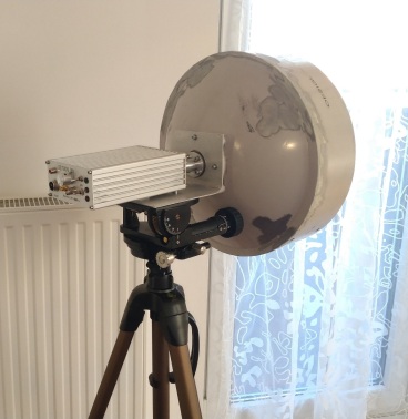
I want to use my 241 GHz system.
1. Offset or prime focus dish?
It depends on accuracy of dish surface (roughness and shape of parabol).
Ruze's equation:
G = -685 * (RMS / Lambda)² ... gain loss due to inaccuracy
RMS ... accuracy of surface
e.g. dish surface RMS = +/- 0.05 mm
G = -1.7 dB @300 GHz
G = -4.8 dB @500 GHz
e.g. dish surface RMS = +/- 0.1 mm
G = -6.9 dB @300 GHz
G = -19 dB @500 GHz
My experience is that a high quality offset dish is much better than a prime focus dish. The reason is that an offset dish has no blocking area due to the feed and the feed sees only the cold sky at low elevations.
Some OE ham colleagues use high precision prime focus dishes (40 cm) made of steel on a lathe (surface accuracy better than 0.05 mm). This dish can be used up to 500 GHz without any big losses.
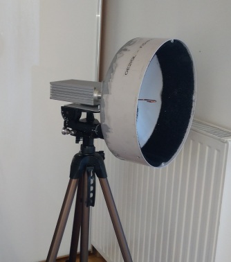
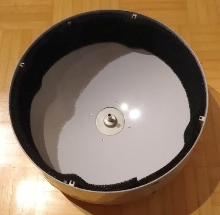
My 63 cm offset dish has too much loss. Therefore I use a smaller prime focus dish (30 cm) from a 38 GHz link station at 122 GHz and higher. It has a f/D = 0.3 and focus distance is 90 mm.
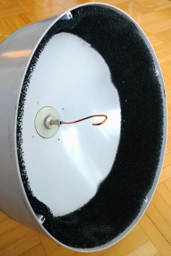
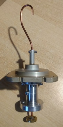
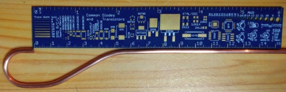
Only the feed needs to adjust for a frequency of 122 GHz and higher. I use a copper tube with outer diameter of 3 mm and inner diameter of 2.1 mm. Cut-off frequency is around 90 GHz.
I bended this tube to form a "Shepherd's Hook" with open end aperture to illuminate my prime focus dish perfectly.
Tripod is a simple one in combination with my old pan/tilt system:
![]()
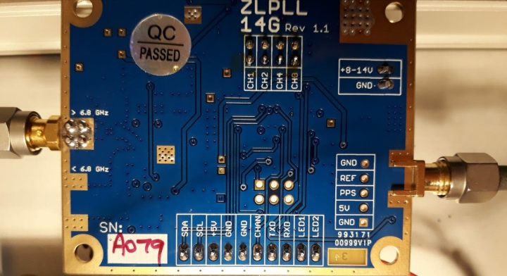
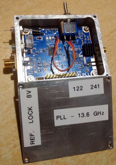
2. PLL output up to 13.6 GHz
My prefered solution is to use the ZLPLL14G made by ZL2BKC. It uses a µ-controller and the ADF5355 too but there is already
a power amplifier on board to get 12-15 dBm output. Additionally it is possible to store up to 16 frequencies and switch from one to another stored frequency within 1 sec. Connection to the board is done via
tera term software. External reference signal (> 10 MHz, 5-14 dBm) is needed and accuracy of output frequency is better than 1 Hz with GPSDO.
Highest available frequency is 14.3 GHz with an output power of approx. 11 dBm.
Modification:
- Change 0 Ohm resistor R8 (power supply output amplifier AVA183 MMIC) against 50 Ohm potentiometer to adjust output power for best Rx/Tx performance
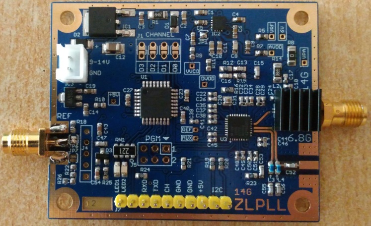
LED2 at bottom side can be used as "PLL locked" signal.
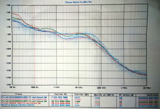
Phase noise:
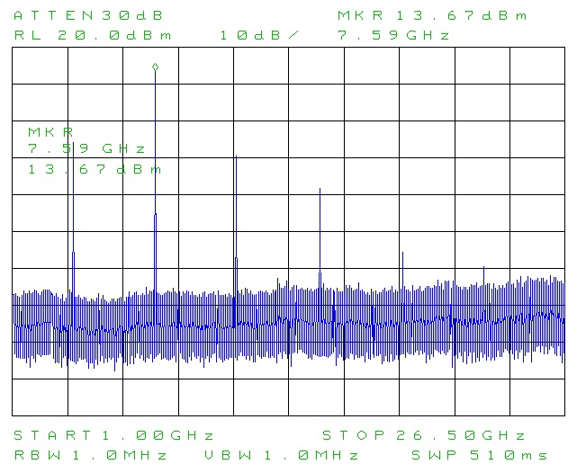
Harmonics:
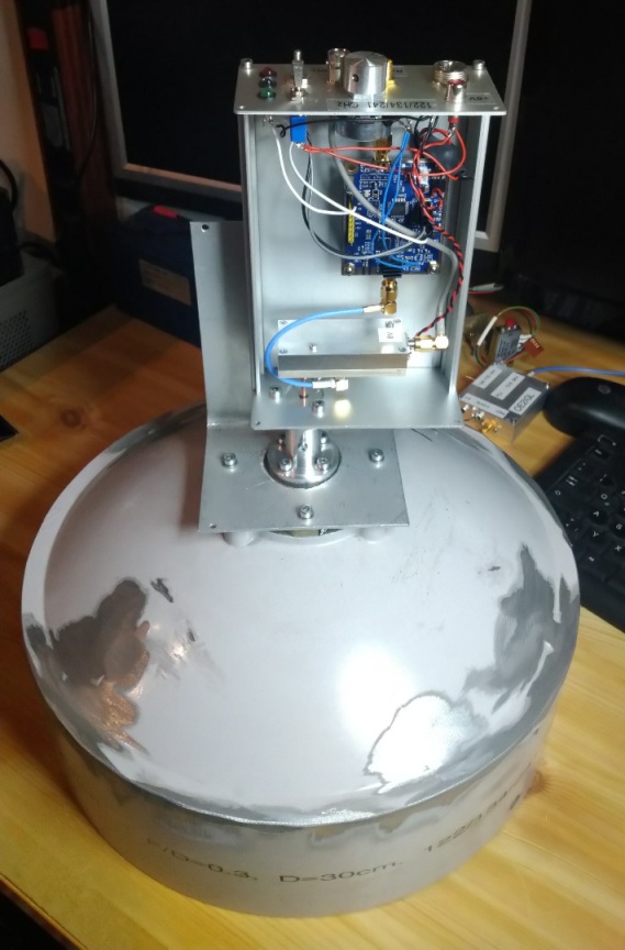
I made an aluminium housing 70 x 60 x 23 mm for this synthesizer PLL.
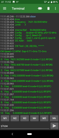
Programming of the ZLPLL14G is done via serial USB terminal software. It is possible to use "Tera Term" in combination with a computer or a smart phone app like "serial USB terminal".
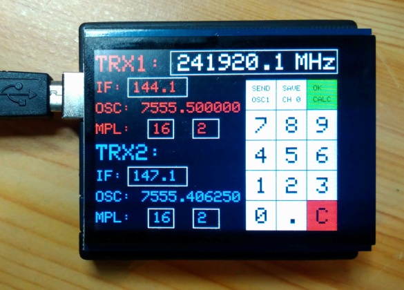
For easier programming of the ZLPLL I made a tool to calculate ZLPLL output frequency depending on RF frequency, IF and multiplier factor for both stations or a beacon. After calculation it is possible to send desired frequency to ZLPLL and save it to a channel.
The tool is an Arduino UNO with a capacitive 2.8" touch screen.
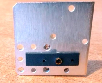
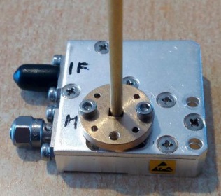
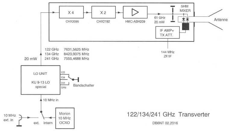
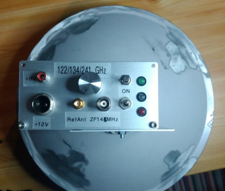
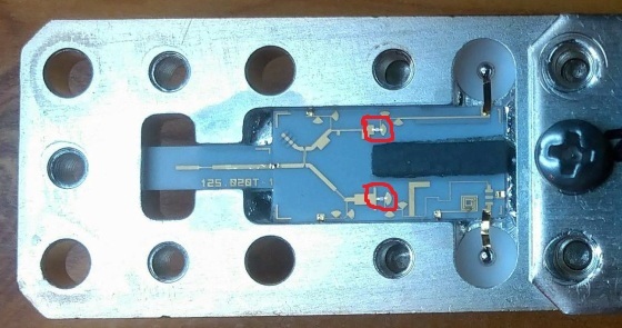
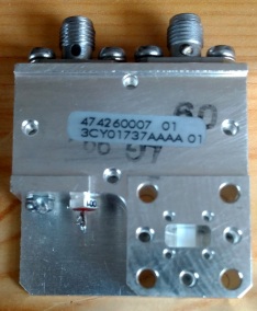
3. Triband mixer & IF interface
This module was made by Michael, DB6NT.
IF Tx-power should be <3 W and LO-power should be around 12 mW. Output is a WR-8 waveguide.
Power supply: 8V
![]()
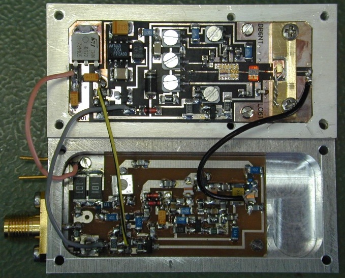
To drive the CHX2095 adaquate the output power from the PLL should be around 11 - 12 dBm.
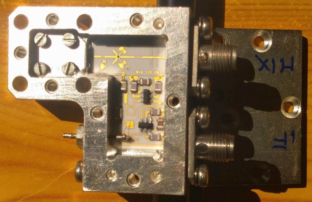
As first stage the transverter uses a by 4 multiplier (CHX2095). Input range is from 6.25 - 8.25 GHz (8.5 GHz is possible), output from 25 - 33 GHz.
Second stage is a by 2 multiplier (CHX2192). Input range is from 25 - 33 GHz, output from 50 - 66 GHz. Above 33 GHz the output signal drops too much.
Last stage uses an 52 to 66 GHz HMC-ABH209 amplifier. Above 66 Ghz the signal drops too much.
Therefore max. input frequency is 8.25 GHz.
8.25 * 4 * 2 = 66 GHz
In the harmonic mixer the signal is then multiplied by factor 8 (factor 2 gives 122 GHz, 4 gives 241 GHz).
Then the maximum output frequency is 66 * 8 = 528 GHz.
Maybe harmonic mixer factor of 10 is possible to get a signal.
Then the maximum output frequency is 66 * 10 = 660 GHz.
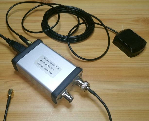
4. GPS disciplined reference oscillator to drive PLL board
Here I use a GPSDO by Leo Bodnar.
It has 2 outputs (3.3V CMOS level) from 450 Hz to 800 MHz and it uses GPS receiver for very stable output frequency.
Output power up to 13.7 dBm
Current consumption @ 12V DC: 190 mA
I use an output of 94.86 MHz to drive PLL board. Therefore I can use same Mini-GPSDO as for my 76 GHz transverter.
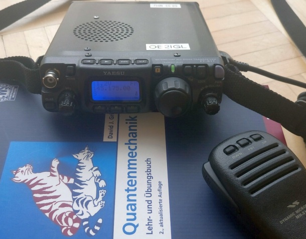
5. IF receiver/transmitter
Therefore I use a FT-817. I have upgraded my FT-817 with an additional IF output. In combination with e.g. SDR# and a Lenovo Convertible Miix 320 Tablet
computer I can find small signals to adjust frequency and dish orientation.
6. Test beacon from 122 GHz to beyond 300 GHz
For first tests and adjustments I need a CW transmitter. Again I use a ZLPLL14G to get a strong signal from 6.8 - 13.6 GHz.
1st version:
The ZLPLL14G signal is feeded into the tripler CMA382400AUP and the tripler produces a 36 - 41 GHz output signal (up to 20 dBm).
The next stage is a 38 GHz Alcatel harmonic mixer. Inside there are 2 very, very small diodes. Just over one diode I made a 1 mm hole in the lid. Additionally I made two M2 threads
for a wave guide flange.
e.g.
13.5833444 * 3 = 40.7500333 GHz -> *3 = 122.2501 GHz
13.4400056 * 3 = 40.3200167 GHz -> *6 = 241.9201 GHz
![]()
![]()
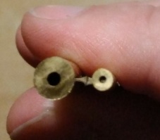
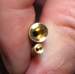
I bought a brass tube for 122 GHz (outer diameter 6 mm/inner diameter 2.0 mm) and another one for 241 GHz (outer diameter 3 mm/inner diameter 1.0 mm). Then I drilled holes in
a WR12 flange, put the tube into the hole and soldered both parts together. With the use of a lathe I made the greater aperture to get a dual mode horn.
Brass tubes before and after:
2nd version:
Again a 38 GHz mixer (3CY01737) and I coupled out the harmonic signal above the tiny mixer diode.
I used a 3 mm brass pipe with an inner diameter of 1 mm. Then I formed a funnel (from 2.6 to 1.0 mm) with the drilling machine on one side.