Antenna and Feed simulation
The basics of prime focus and offset dishes can be found in "The W1GHZ Online Microwave Antenna Book".
Paul Wade has written an excellent antenna book with a lot of detailed explanations about different feeds. Paul also made a lot of simulations for each feed.
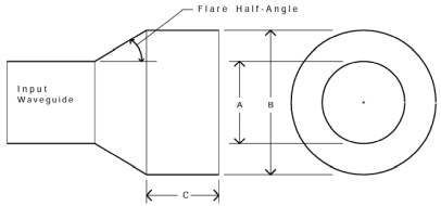
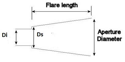
Formula to calculate a dual mode horn for an offset antenna: e.g. 76 GHz

Simulation by W1GHZ:
Nowadays it is easy to make such simulations without any extra costs at home. Only your computer speed/memory limits your own simulations.
I use open software OpenEMs and Octave to do my own feed simulations.
On the OpenEMS website there are tutorials available with a lot of simulation examples.
Another commercial software is CST studio suite. There is a free student version available but it is limited to max. mesh cells of 100 000.
That is too less because I need between 10 000 000 and 500 000 000 mesh cells.
The student edition of GRASP (GRASP-SE) by TICRA is also very useful and good tool to simulate the feed/reflector system using the feed simulation output of OpenEMS.
I tried Ansys HFSS student, QuickWave student and CENOS too, but I was not happy.
15th of February 2025: Talk "Free simulations of feed and reflector antenna for highest performance" at Dorsten GHz conference in Germany
Click here (only available in German) -->


Concept of free simulations:

28th of February 2026: Talk "Axial-corrugated horn for highest performance higher than 10 GHz" at Dorsten GHz conference in Germany

1. Here are some of my simulations with openEMS, GRASP-SE and free CST
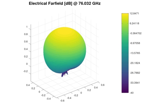
Dual Mode Horn @76 GHz, optimized for an offset dish f/D=0.66:
OpenEMS simulations: Resolution was done with lambda/60. Material is brass.

I can see the ripple of farfiled directivty only if I use AddMaterial and SetMaterialProperty command (instead of AddMetal command).


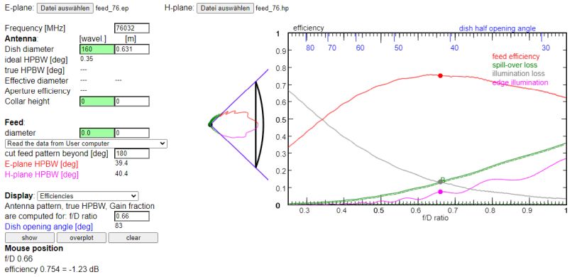
Using Joachim's DF3GJ tool and the far field feed pattern (outcome openEMS) it is possible to calculate illumination and spillover efficiency of the dish.
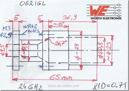
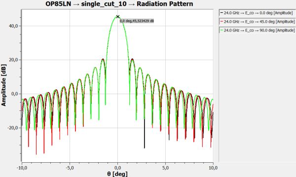
Dual Mode Horn @24 GHz with f/D=0.71, optimized for a f/D=0.66 offset dish:
For this I used the free CST version to simulate my dual mode feed. After that I used feed pattern in combination with GRASP-SE to simulate feed/offset dish system.
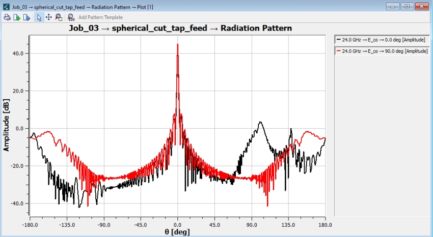
As GRASP-SE can not simulate with real feed pattern (only full version) GRASP-SE uses "simple tapered pattern" mode. Tapered pattern values come from the CST feed simulation.
CST feed simulation:


GRASP-SE offset dish simulation:

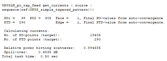
Spillover efficiency = 89.5%
Illumination efficiency = 87.1%
Gain = 45.16 dBi
2. Simulations with GRASP-SE (student edition) & comparison with GRASP full version
Comparison between GRASP-SE and full version of 0.85 cm offset reflector antenna:
-
GRASP full version: Dual mode horn f/D=0.71, 0.85 cm offset reflector f/D=0.66
This simulation was done by Willi HB9PZK.
Gain is 45.46 dB.

-
GRASP-SE (student version): sim mode "simple tapered pattern" using dual mode horn pattern, 0.85 cm offset reflector f/D=0.66
Gain is 45.51 dB. Sim mode "simple tapered pattern" is a very accurate mode in GRASP-SE comparing to full version with real feed pattern.
Gain difference is only 0.05 dB.

-
GRASP-SE (student version): sim mode "gaussian feed" using taper -10 dB, 0.85 cm offset reflector f/D=0.66
Gain is 45.52 dB. Sim mode "gaussian feed" is a very accurate mode in GRASP-SE comparing to full version with real feed pattern.
Gain difference is only 0.06 dB.
Comparison between 2.4 m prime focus and 2.4 m offset antenna @47 GHz:
This was done with GRASP full version and GRASP-SE to see the difference. Only full version is able to simulate feed/struts but at least with a trick it is possible to simulate a feed with GRASP-SE.
Because the real feed pattern was not available a gaussian feed pattern with -12 dB taper was used.
These simulations were done by Willi HB9PZK.
-
2.4 m prime focus antenna (f/D=0.4, -12 dB taper): GRASP full version
Without feed/struts blocking, gaussian feed

With feed blocking, gaussian feed

With feed and struts blocking, gaussian feed

-
2.4 m prime focus antenna (f/D=0.4, -12 dB taper): GRASP-SE
With feed blocking, gaussian feed -
2.4 m offset antenna (f/D=0.65, -12 dB taper, gaussian feed):
There isn't any feed/struts blocking.

Offset reflector has 0.4 dB higher gain than same prime-focus reflector.

3. High-performance feeds for offset reflector antenna with OpenEMS
I simulated feeds from 10 to 47 GHz and f/D >0.5 with OpenEMS, but it should work for higher frequencies too. Then I created a design guide with the simulation results.
Now it is easier to get well performing feeds without a simulation software.
Antenna efficiency (product of illumination, spillover, polarization and phase error efficiency) is between 78%-80%. Pickett-Potter is slightly better than W2IMU feed.
"Dual Mode Horn design guide"
Turrin W2IMU dual mode horn:
Pickett-Potter dual mode horn:
4. High-performance feed for prime focus reflector antenna with OpenEMS
For a prime focus reflector antenna with f/D < 0.5 a cavity feed is a very good choice.
Antenna efficiency (product of illumination, spillover, polarization and phase error efficiency) up to 83% is possible.
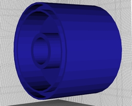
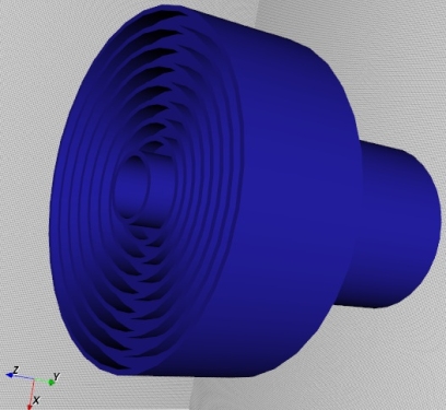
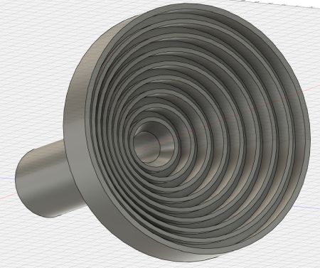
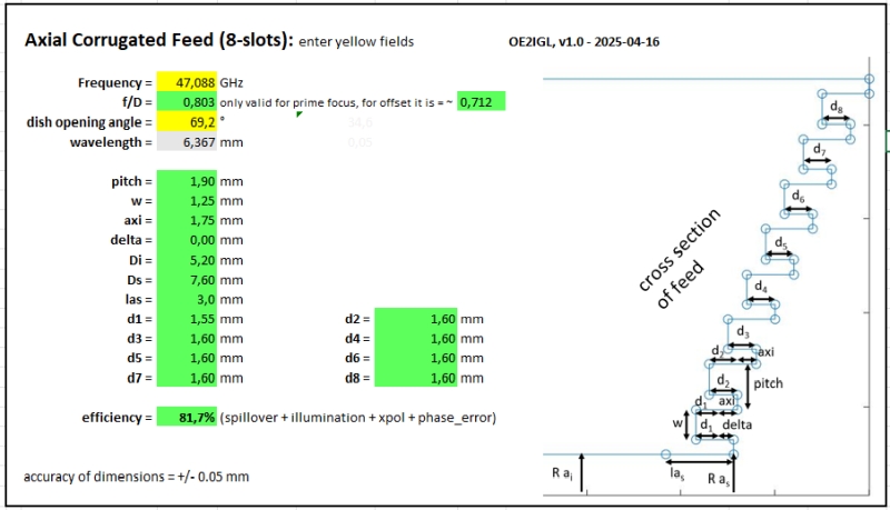
5. Axial-corrugated high-performance feed for prime focus & offset reflector antenna with OpenEMS
A corrugated feed provides best performance over a wide range of dish opening angle (f/D), from 0.3 to 0.8. Different types are availabel, axial-corrugated, radial-corrugated and axial-radial-corrugated feed.
The axial corrugated version is easy to manufacture and CT1DMK showed me the way.
Antenna efficiency (product of illumination, spillover, polarization and phase error efficiency) is between 81%-86%, depending on f/D.
click to download the design guide:
6. Lambda/4 matching transition with OpenEMS
I simulated lambda/4 transitions from 10 to 47 GHz with OpenEMS, but it should work for higher freqiencies too. Then I created a design guide with the simulation results.
Now it is easier to get weel performing transitions without a simulation software.
S11 is lower than -30 dB.
"quarter waveguide transition design guide"
![]()
![]()
7. Other simulations with openEMS
Coax to rectangular waveguide transition @10.368 GHz:
WR90 waveguide.

Backshort (distance back wall to coax pin) : 6.1 mm
Coax pin length (inside of wave guide) : 5.73 mm

Coax to circular waveguide transition @10.368 GHz:
Copper pipe with inside diameter of 20.1 mm.
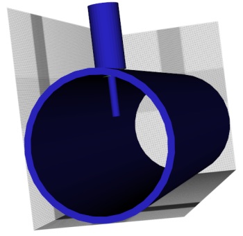
Backshort (distance back wall to coax pin) : 12.0 mm
Coax pin length (inside of wave guide) : 6.3 mm
Length between coax pin and open end : 53.3 mm (= 1x wave guide wavelength)
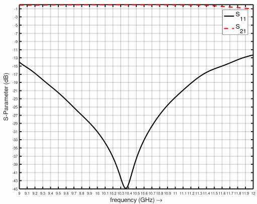
The end cap is moveable to adjust S11.