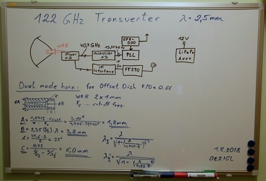
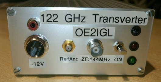
122 GHz transverter
Let's try a harmonic mixer concept designed by Philipp DL2AM and Michael DB6NT.
It is based on article "122.250 GHz transverter technique" by Philipp DL2AM in
Dubus 2/2018.
Tx output : 30 - 100 µW (multiplier and IF mixer)
1 - 2 mW (only multiplier for beacon)
RX NF : > 20 dB
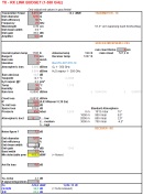
Click on image, download and extract my Excel sheet "Link budget v2.1" to calculate microwave links up to 1000 GHz. Calculation of atmospheric attenuation (ITU-R P.676-12) is included.
1. Offset dish and tripod with pan/tilt mount
Same design as for my 76 GHz transverter and pan/tilt head.
A TVSat offset dish for 11 GHz is not the best solution for 122 GHz because of poor surface accuracy, additional loss is around 10 dB. But let's try, otherwiese
I have to use a link station dish for 37 GHz.
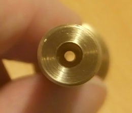
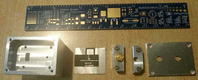
2. W2IMU Dual mode feed horn
hdl_ant software by W1GHZ is a good choice to calculate a dual mode feed horn. It is a circular wave guide with a diameter of 1.8 mm and the aperture is 3.8 mm (depth
of 6 mm).
Wave length = 2.45 mm
WR-8 : 2 x 1 mm
3. PLL with 13.5 GHz output
I use a modified NORT PLL to obtain 13567.3333 MHz for the transverter input. I removed the internal 20 MHz quartz and mounted a SMA connector which is an external
reference input now.
See more under electronics.
13567.3333 * 3 * 3 + 144 IF = 122.250000 GHz
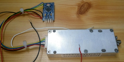
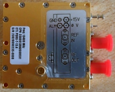
Another solution is a 13.4 GHz PDRO from CTI locked to 13.5673333 GHz, REF-In could be a 135.673333 MHz signal.
Current consumption @ 12 - 15V DC: 240 mA
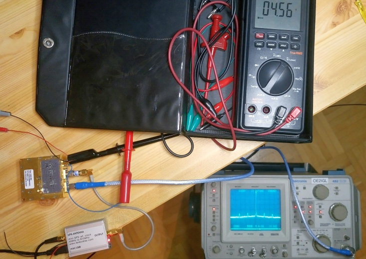
Signal locked output : 4.6 V
RFout = 14.5 dBm
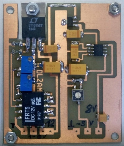
4. Triple multiplier module and power supply PCB
Multiplier CMA 382400
Input: 13.5673 GHz, 14.5 dBm
Ouput: 3 x 13.5673 = 40.702 GHz, max. 100 mW
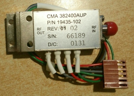
Power supply for triple multiplier for TX and RX mode.
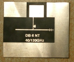
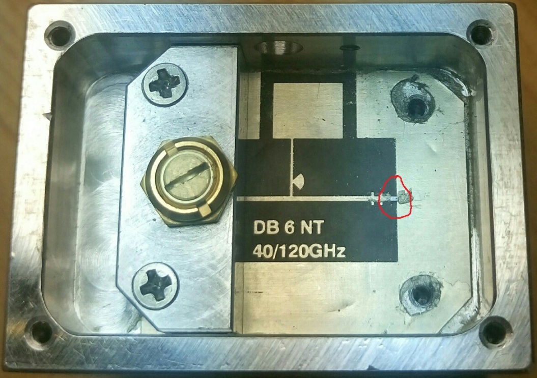
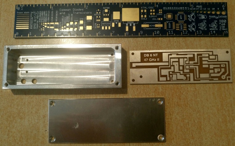
5. Harmonic mixer
PCB no.47 made by Michael Kuhne DB6NT and a MA4E1310 single diode as subharmonic mixer.
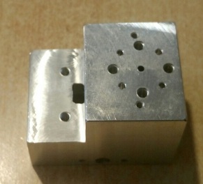
Mixer housing
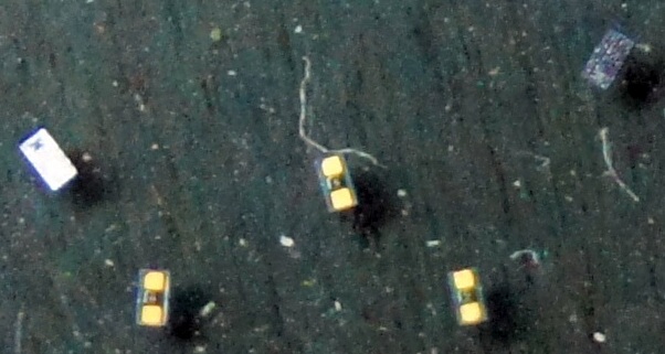
MA4E1310 single diode: Here you can see 5 diodes, each 0.6 x 0.3 mm
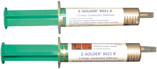
At first I glued the mixer PCB with silver conductive adhesive solder (e.b. E-solder 3021A and 3021B) into the housing. Then I put the housing in an
oven for 1-2 hours at 80°-100°C.
With the use of a stereo microscope I glued the diode on the mixer PCB. Use only a very very small
drop of silver glue for both solder pins. Therefore I used a very thin needle. Again put the housing in an oven for 1-2 hours at 80°-100°C.
6. IF module
PCB no.26 made by Michael Kuhne DB6NT.
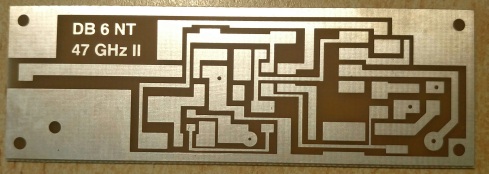
IF module housing
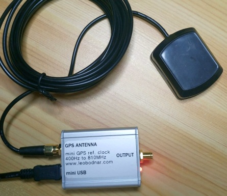
7. GPS disciplined reference oscillator to drive NORT or PDRO module
Here I use a nice Mini-GPSDO by Leo Bodnar.
It has 1 output (3.3V CMOS level) from 450 Hz to 800 MHz and it uses GPS receiver for very stable output frequency.
Output power up to 13.7 dBm
Current consumption @ 5V DC: 200 mA
Output frequency is 135.673333 MHz to drive PDRO from CTI
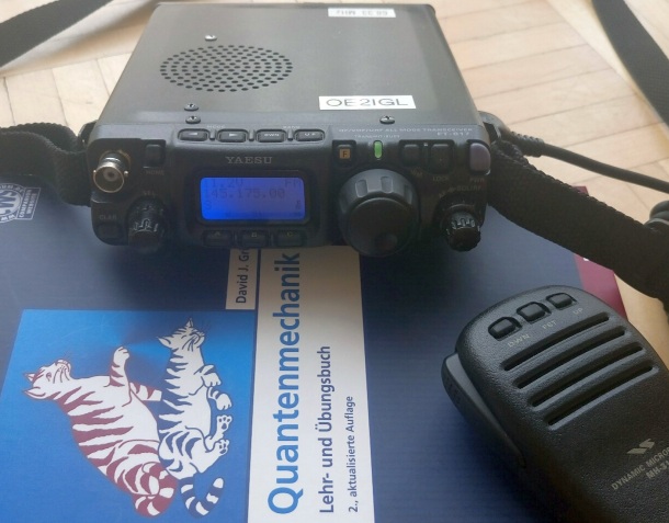
8. IF receiver/transmitter
Therefore I use a FT-817. I have upgraded my FT-817 with an additional IF output. In combination with e.g. SDR# and a Lenovo Convertible Miix 320 Tablet
computer I can find small signals to adjust frequency and dish orientation.
9. Accu pack
I use a 12V LiFePO4 accu with 10Ah because of its light weight, only 1.4 kg.