Azimuth & elevation system for mobile use
1. Azimuth system
At higher frequencies and with bigger dishes -3dB beam width gets smaller and smaller. E.g. for 76GHz with a 60cm dish it is around 0.6°.
Therefore a stable azimuth system with fine adjustment is essential.
1st version:
Dish rotation was done manually by hand without any fine adjustment system.
2nd version:
Not stable enough and without azimuth scale. Coarse (0-360°) and fine adjustment (+/- 5°). One screw rotation is approx. 0.75°.
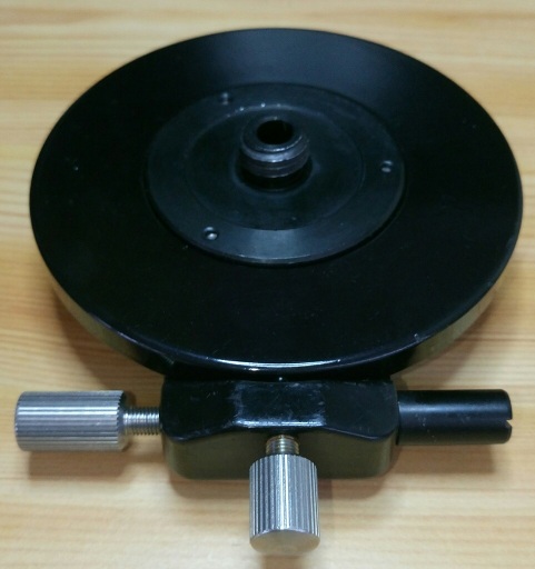
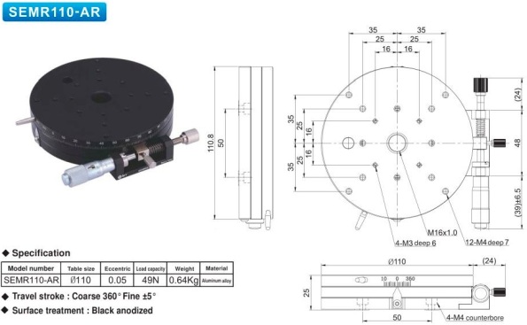
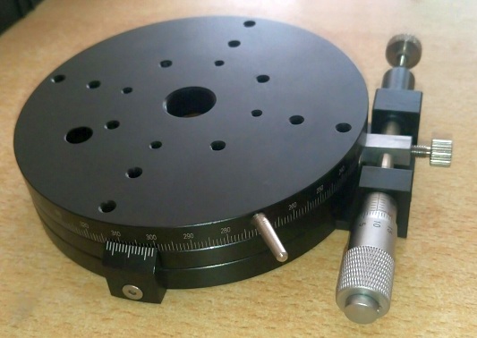
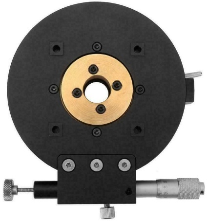
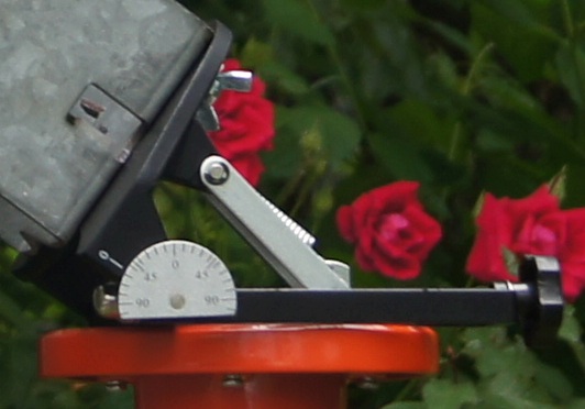
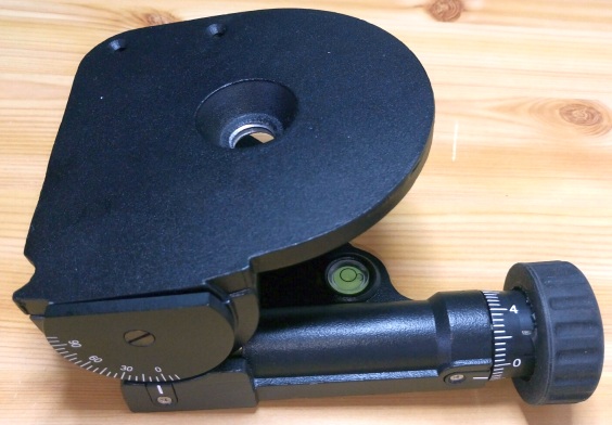
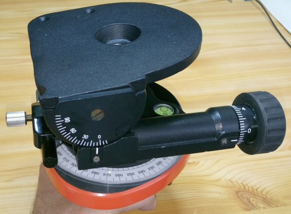
3rd version:
With coarse (0-360°) and fine adjustment (+/- 5°). One screw rotation is approx. 0.50° and azimuth angle resolution is approx. 0.01°. Now with an azimuth scale to read angle and it is very stable. Max. load should only be 50N (5 kg).
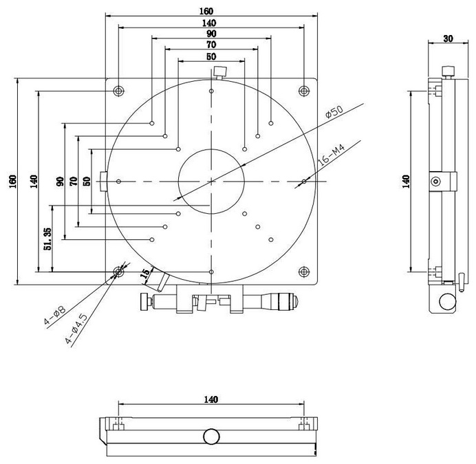
4th version:
The SEMR160-AR is the bigger brother of 3rd version with a diameter of 160 mm. Big advantage is that the load could be up to 390 N (max 39 kg), but it is heavier (2.2 kg).

2. Elevation system
At higher frequencies and with bigger dishes -3dB beam width gets smaller and smaller. E.g. for 76GHz with a 60cm dish it is approx. 0.6°.
Therefore a stable elevation system with fine adjustment is essential.
1st version:
Backslash was not small enough, not stable enough and elevation scale was only roughly.
2nd version:
Backslash was better but not small enough. It has a fine tuning screw with scale (0.1° accuracy).
3rd version:
Stable spindle system with digital tilt meter (0.1 accuracy). One spindle rotation is approx. 1.5° and therefore elevation angle resolution is down to 0.02°.

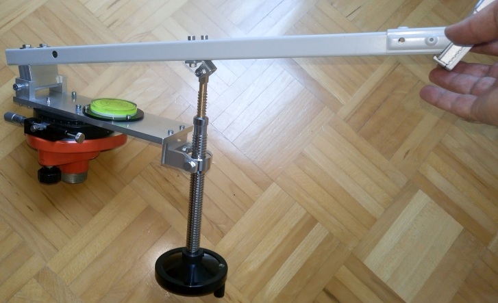
3. Manual azimuth-elevation system
Old 2nd version for my tripod:
Resolution azimuth: 0.025°
Resolution elevation: 0.1°
Finished 3rd version for my tripod:
Resolution azimuth: 0.01°, 0.45°/screw rotation
Resolution elevation: 0.02°, 1.5°/screw rotation
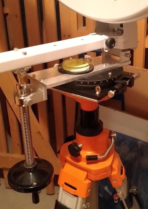
Finished 4th version for my tripod:
Now for a heavier load
Resolution azimuth: 0.01°, 0.45°/screw rotation
Resolution elevation: 0.02°, 1.5°/screw rotation
4. Motorized azimuth-elevation system
For EME or sun/moon noise measurements a stable and accurate tracking system is a great help.
1st version:
See more here
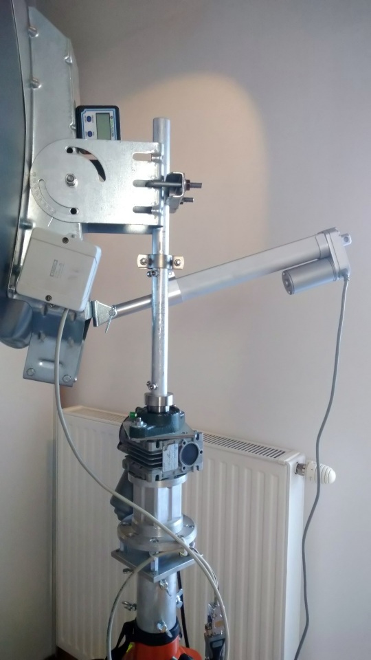
2nd version:
This version is an update of version 1. It is based on version 3 of my manual system but uses a worm gear DC motor for azimuth (+ encoder) and an actuator DC motor for elevation (+ inclinometer). It is more stable and in future I will use a new controller system.

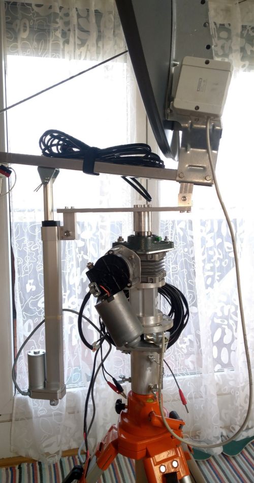
5. High accuracy, motorized azimuth-elevation system for EME at higher frequencies
At higher frequencies (>24 GHz) and/or bigger dishes the half-power-beam width is around or smaller than sun/moon diameter (0.5°).
To get maximum signal level a very accurate tracking system is needed. This is very important for EME because there are 2 stations (Rx and Tx) and both stations (small antenna beams)
must meet at an exact point on the moon. EA3HMJ has developed such a high accuracy tracking system.
Power supply and current consumption: 12V or 24V, ~100 mA (only board without motor consumption)
Azimuth/elevation accuracy: <0.03°
![]()
Version v2.3 with ethernet connection:
![]()
![]()
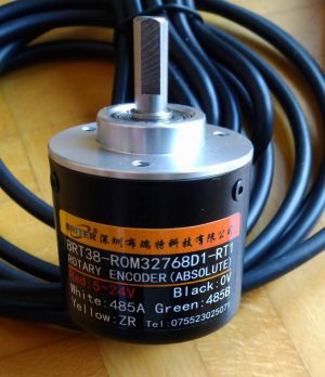
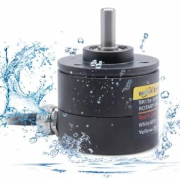
BRT38-R0M32768-RT1 absolut-encoder with 15 bit or the waterproof 16 bit version BRT38-R0M16bit-RT1-IP68.
See here https://briterencoder.com/
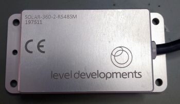
SOLAR-360-2-RS485M - inclinometer sensor from level developments.
See here https://www.leveldevelopments.com/
In combination with such a DC-motor for elevation & azimuth from coresundrive.
![]()
6. Improvement of antenna pointing accuracy
There are a lot of inevitabile small errors in the pointing of an antenna, such as tilts of the axis, encoder offsets, gravitational bending, ...
Most of the causes and the amount of these effects are unknown or the remaining errors can't be reduzed by further mechanical adjustments.
The good thing is that it is possible to reduce these errors by software dramatically. For that a pointing model is used.
1st step: determine the real azimuth/elevation position vs. given azimuth/elevation (encoders)
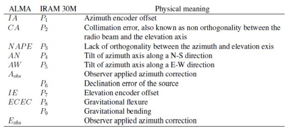
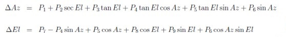
2nd step: define a pointing model. Either the P-model with up to 9 parameters describing the most known effects (given by trigonometric sin/cos functions for azimuth adn elevation)
or a more sophisticated model using all sin/cos combinations and also higher frequency terms (sin(2x),cos(2x),sin(3x),cos(3x),...).
3rd step: calculate the parameters for the model using the deviations determined in step 1. You can use the Simplex methode or the "solver" function in Excel.
4th step: use the correction equation to adjust used azimuth/elevation values
Joachim Koeppen DF3GJ described this approach in DUBUS 4/2015 "Pointing Corrections for Large Radio Antennas". This approach is also used for professional radio astronomy antennas and optical telescopes.