EME (earth moon earth) station for 24.048 GHz
I have seen that in the garden of my second home in OE5 (JN68XC) it is possible to set up a fixed mounted station.
Above 12° of elevation from east to west I have free sight to the moon. Only in SW I need more than 27° of elevation because of the house.
EARTH-SPACE ATTENUATION & SKY TEMPERATURE:
Click HERE, download and extract my Excel sheet "Earth-Space-Attenuation" to calculate microwave earth-space attenuation and sky temperatur up to 350 GHz. Calculation of atmospheric attenuation (ITU-R P.676-12) is included. Either with local weather data only or with integrated water vapour content delivered by weather sonde data.
EME link budget and analysis tool:
Click HERE
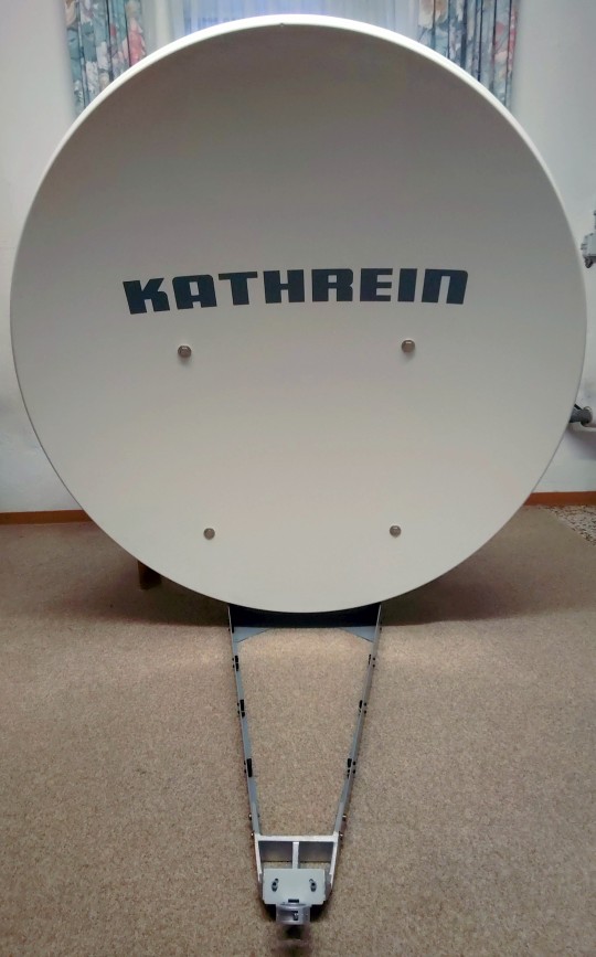
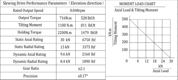
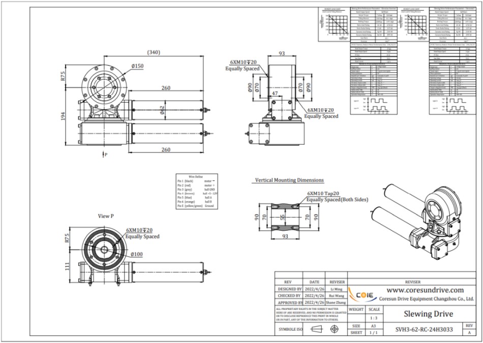
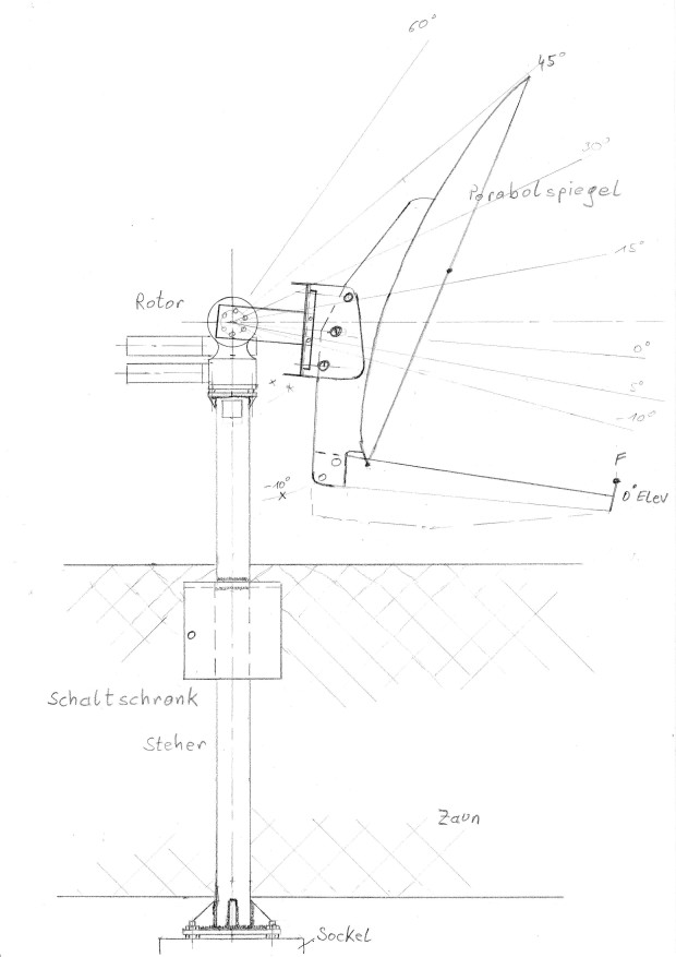
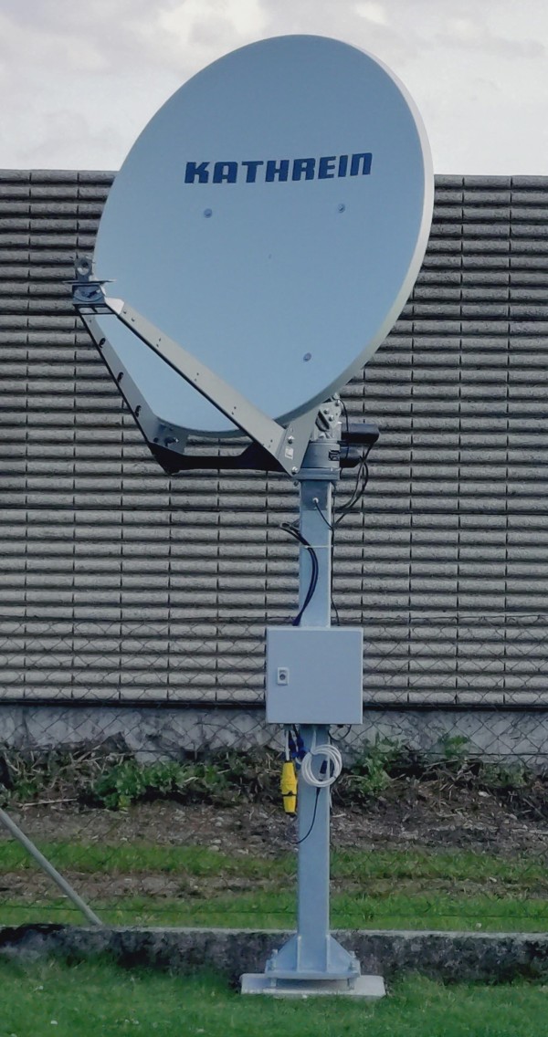
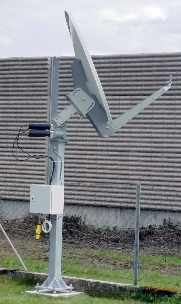
1. Offset dish with azimuth/elevation drive
For that I use a Kathrein CAS120 offset dish with 120 cm in combination with a DC-drive for elevation & azimuth
from coresundrive.
f/D = 0.646
offset angle = 22.8°
surface RMS ~ 0.2 mm
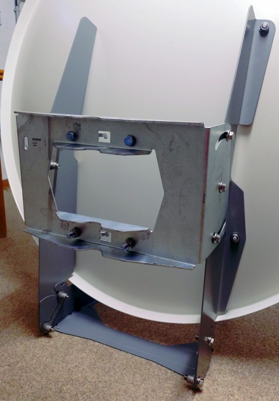
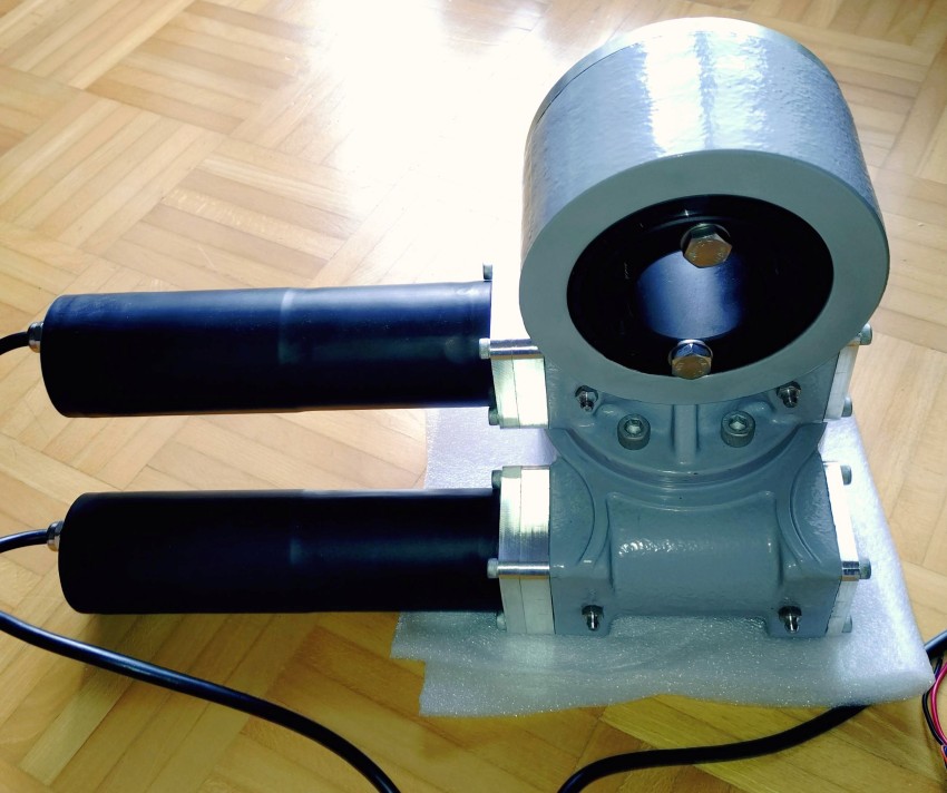
SVH3 dual slewing drive:
Current consumption @24V: 500 mA
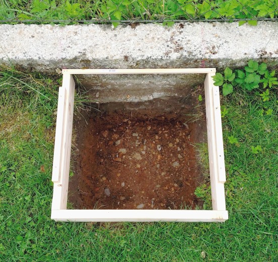
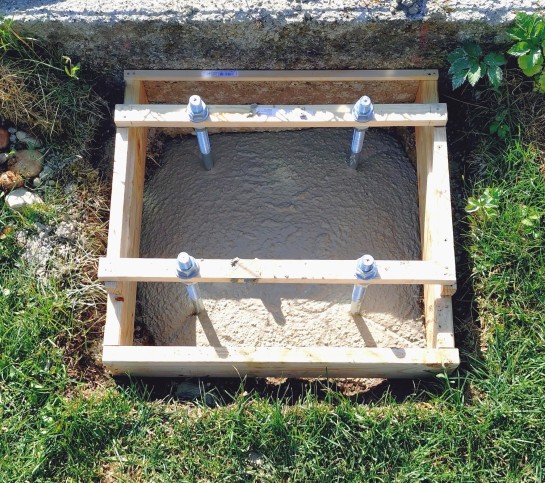
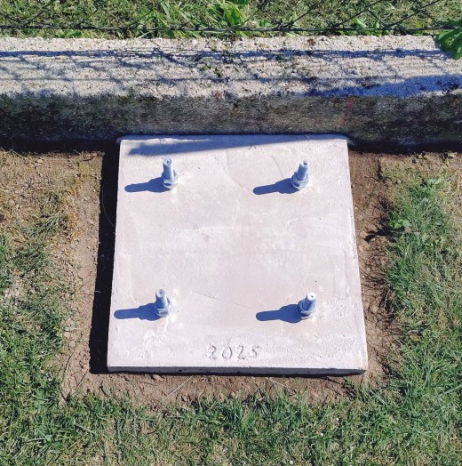
2. Concrete foundation and pillar
The size of the foundation is around 0.45 x 0.45 x 0.6 m. For this I needed ~250 kg ready-mixed concrete and 4x M18 J-screws.
3. EA3HMJ dish rotor controller
At higher frequencies (>24 GHz) and/or bigger dishes the half-power-beam width is around or smaller than sun/moon diameter (0.5°).
Power supply and current consumption: 12V or 24V, ~100 mA (only board without motor consumption)
Azimuth/elevation accuracy: <0.03°
See here https://github.com/EA3HMJ-Tracking-Software-Suite
![]()
Version v2.3 with ethernet connection:
![]()
![]()
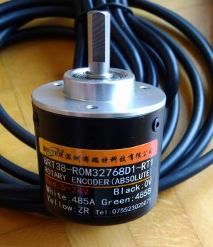
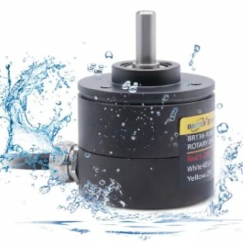
BRT38-R0M32768-RT1 absolut-encoder with 15 bit or the waterproof 16 bit version BRT38-R0M16bit-RT1-IP68.
See here https://briterencoder.com/
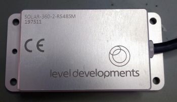
SOLAR-360-2-RS485M - inclinometer sensor from level developments.
See here https://www.leveldevelopments.com/
![]()
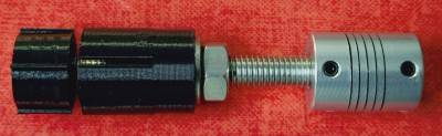
I use a 3D printed dowel to fix an azimuth shaft and a clutch under the azimuth slewing drive. With this solution it is easy to connect an azimuth encoder.
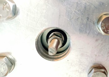
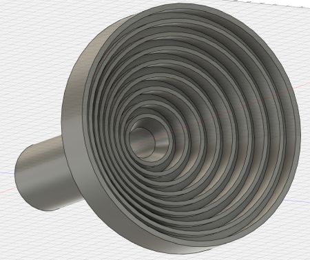
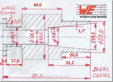
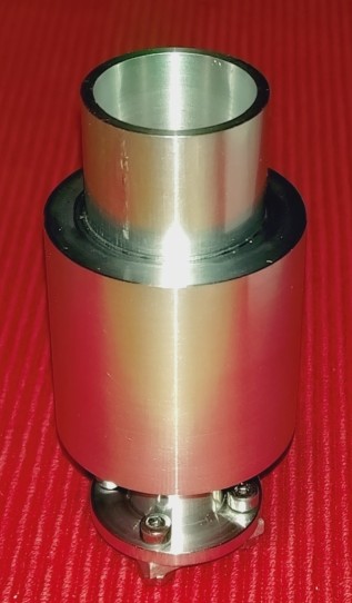
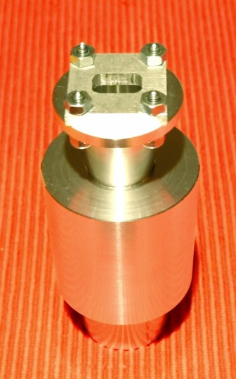
4.1 High-performance axial-corrugated feed
I have simulated this feed for highest G/T. A feed design for f/D = 0.71 in my dish with f/D = 0.65 gives the best result, more than 81% efficiency.
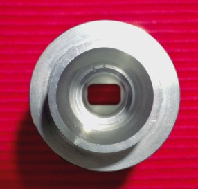
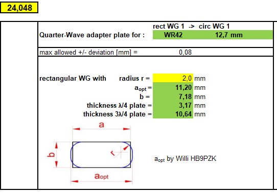
I use a WR42-to-CIR quarter-wave adapter plate to minimize return loss.
See here high-performance axial corrugated feed horn
4.2 Pickett-Potter feed
I have simulated this feed for highest G/T. A feed design for f/D = 0.71 in my dish with f/D = 0.65 gives the best result, more than 79.5% efficiency.
This horn was manufactured by Bert Modderman PE1RKI.
I use a WR42-to-CIR quarter-wave adapter plate to minimize return loss.
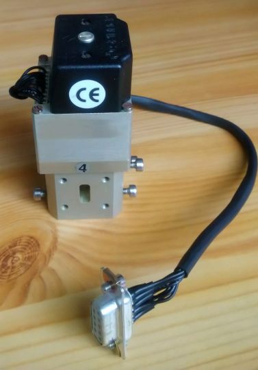
5. Waveguide switch
In front of the feed horn I mounted a WR42 waveguide switch from SPINNER GmbH to minimize signal loss and to have a sufficient decoupling between Tx and Rx.
Current consumption @24V: 500 mA
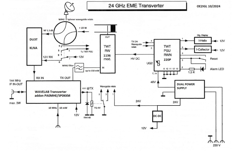
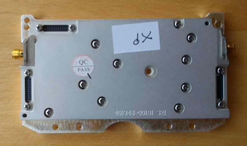
6. Transverter
It is a 23GHz WAVELAB 23x1008xp module bought on eBay.
Tx - PA: 21.2 - 23.6 GHz
Noise figure: 3.5 dB
Output power: max 2W
See here.
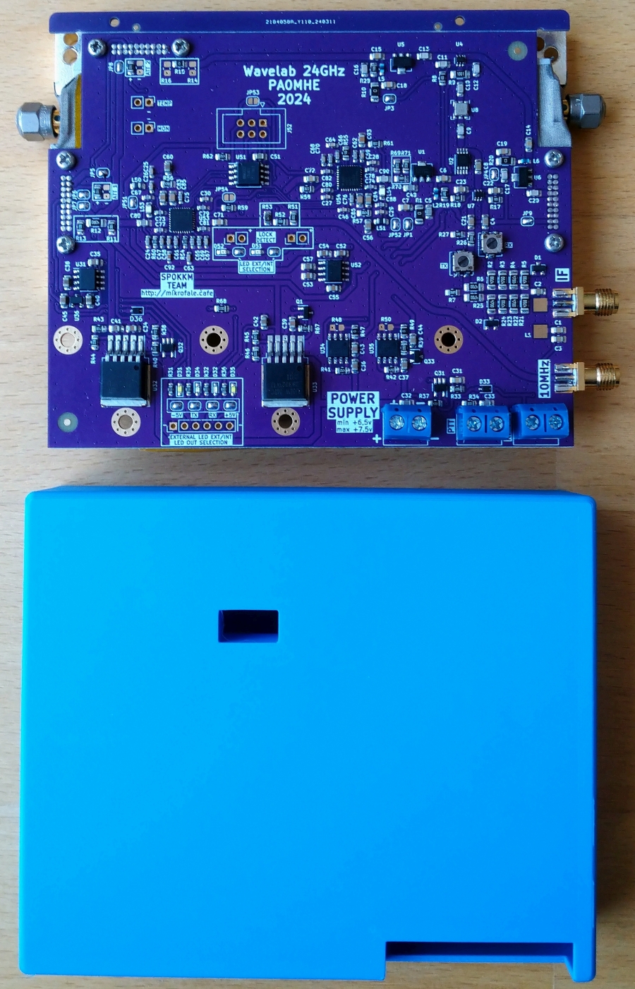
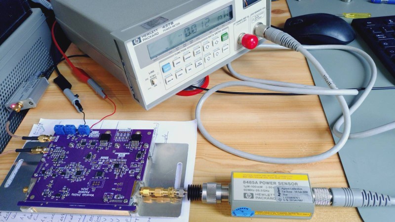
7. PA0MHE wavelab addon PCB
PA0MHE has designed an addon PCB to convert the surplus Wavelab 23 GHz module to 24 GHz ham band.
On Github you will find all information about the Wavelab-24G-Addon-module.
Here is another information by KM5PO about the Wavelab project.
Current consumption of addon board @max. 7.5V: max. 350 mA
Current consumption in combination with wavelab RF module: ~1.3A (Rx), ~2.5A (Tx)
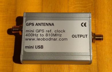
8. GPS disciplined reference oscillator to set 10 MHz reference input
Here I use a nice unit by Leo Bodnar.
It has 1 output (3.3V CMOS level) from 450 Hz to 800 MHz and it uses GPS reveiver for very stable output frequency.
Output power up to 13.7 dBm
Current consumption @ 12V: 270 mA
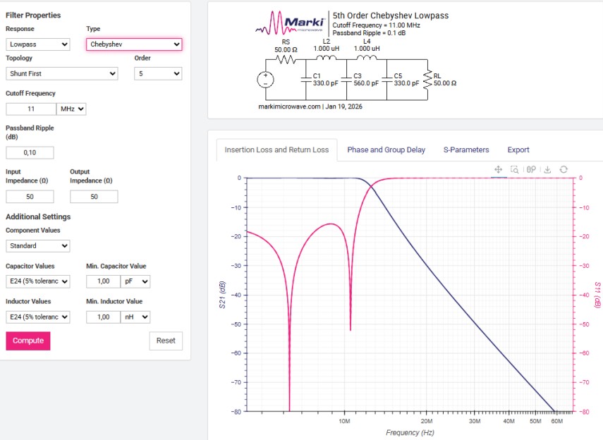
If needed here is a 10 MHz filter for the 10 MHz reference to get clean sine wave signal instead of square wave signal.
9. Preamplifier for 24 GHz
I have a DU3T-KLNA.
Noise figure : 1.3 dB
Gain: 30 dB
Current consumption @ 12V: 105 mA
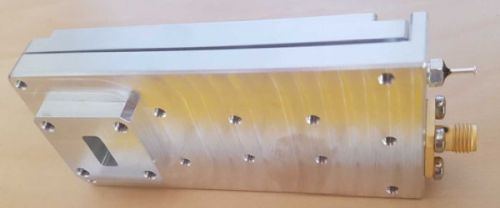
10. Power amplifier for 24 GHz
It is a modified TWT RW1136 by PE1CKK.
Drive power: max. 150mW
Output power: ~17 W
Current consumption @ 48V: max 3 A
Because I use the feedback connection of the waveguide switch I don't need a sequencer.
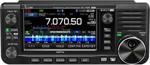
11. IF receiver/transmitter
Therefore I use my modified IC-705 to switch the transverter into TxOut mode.
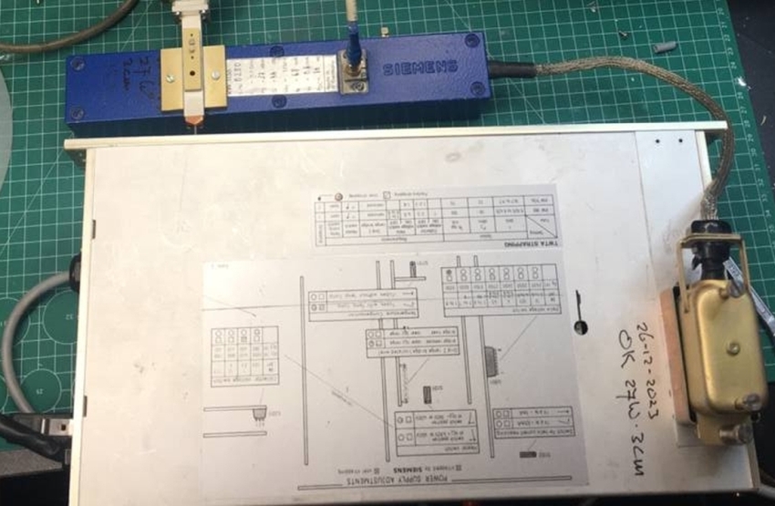
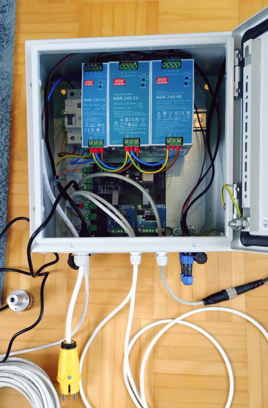
12. Power supply
It is a waterproof Rittal cabinet (300 x 300 mm) for 12, 24, 48 V and the rotor controller board that is mounted on the pillar.
13. Software
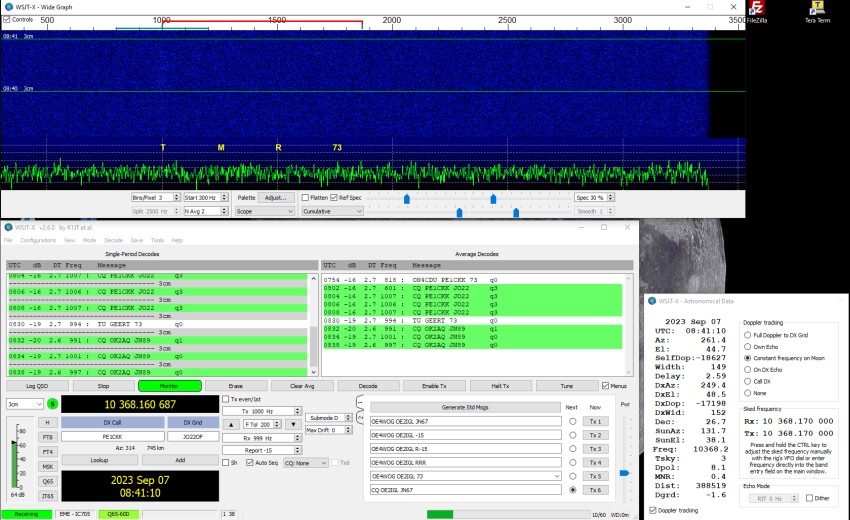
WSJT-X
WSJT-X, developed by Nobel prize winner in physics Joe Taylor K1JT, is an excellent software for weak signal reception.
Mode Q65 is used for 24 GHZ EME and WXJT-X can control my receiver too.
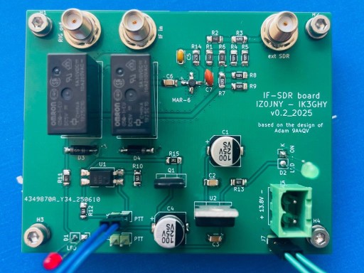
14. IF-SDR board
IF-SDR board, developed by Ivan IZ0JNY, is a board to split RX IF signal into 2 signals.
One for the tranceiver and one for a SDR to measure moon noise in parallel. Tx signal from tranceiver is blocked to the SDR by >50 dB.
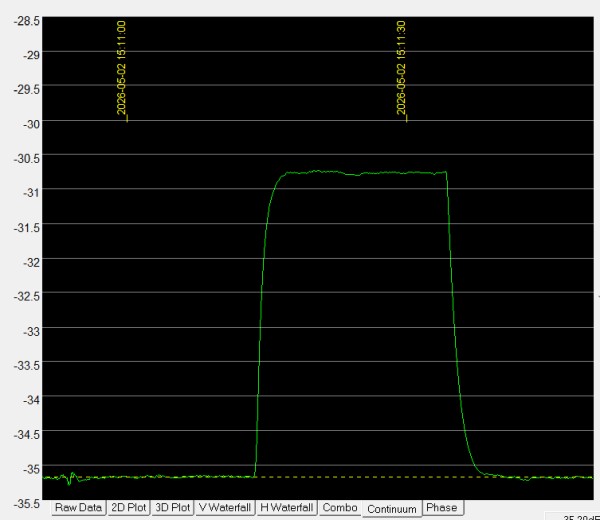
I use SpectraVue and the FUNcube Dongle Pro+ to measure moon/sun noise.
15. Test results
6th of April 2026:
Elevation and azimuth slewing drive tests. First, I aligned the mast so that it was as vertical as possible. Therefore I used a feature in DriverDish software.
During a complete azimuth rotation (elevation below 5°), DriverDish continuously reads and saves the azimuth and elevation position. The data follows a sine curve and now it is possible to see the necessary tilt correction (direction and value).
The mast has a tilt of 0.015°.
For 24 GHz this adjustment is enough. For higher accuracy you should use the method described here (chapter 6).
2nd/3rd of May 2026:
Sun noise measurement and calibration of azimuth/elevation offset finding max. sun noise. For this I use the Funcube Dongle Pro+ (FCD) SDR and the software SpectraVue.
2nd of May:
UTC 15:10, temp 24°C, humidity 17%, abs. pressure 980 mbar, zenith/absorber = 4.41 dB
That gives NF = 1.4 dB
3rd of May:
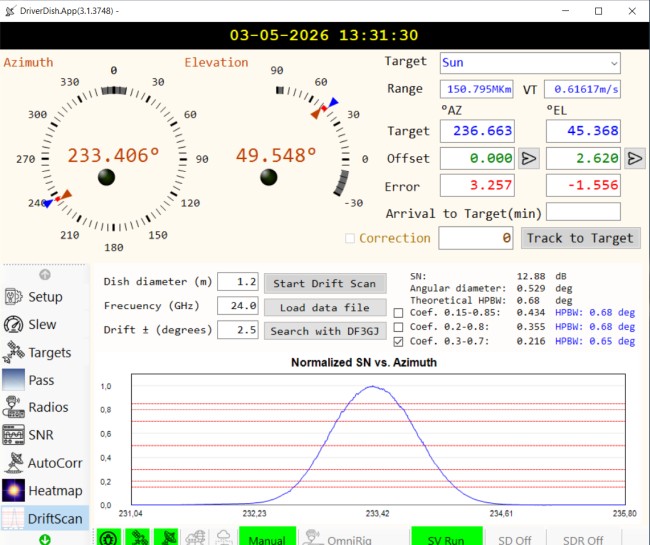
UTC 9:15-9:35, temp 18.5°C, humidity 46%, abs. pressure 983 mbar, SN = 13.1 dB
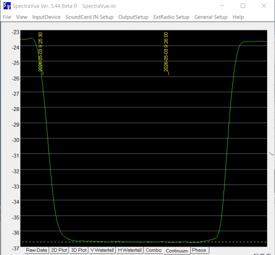
sun drift scan with DriverDish: HPBW 0.68°
??? 2026:
Moon noise measurement and WSJT-X decodes of 24 GHz moon beacon (DL0SHF). First WSJT-X Q65 decodes of other EME stations.
??? 2026:
First WSJT-X Q65 QSO.